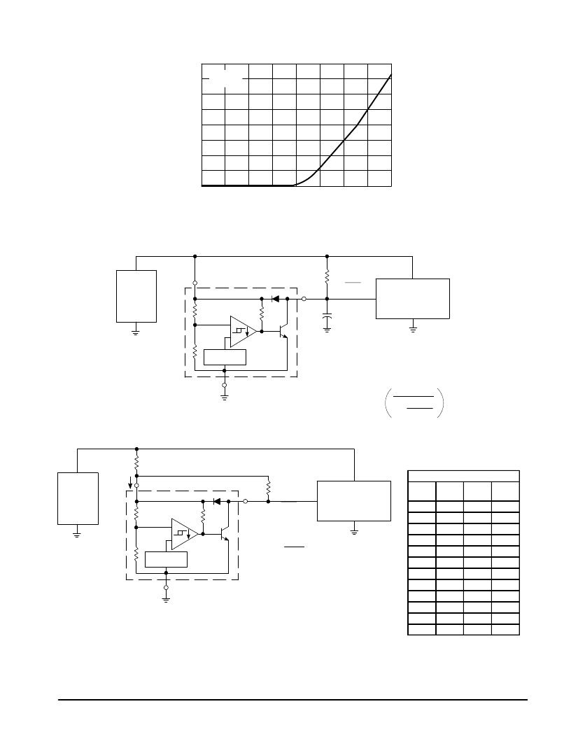
Figure 7. Clamp Diode Forward Current
versus Voltage
Figure 8. Low Voltage Microprocessor Reset
Figure 9. Low Voltage Microprocessor Reset with Additional Hysteresis
80
60
40
20
0
0
0.4
0.8
1.2
1.6
VF, FORWARD VOLTAGE (V)
,
F
I
Vin = 0 V
TA = 25
°
C
A time delayed reset can be accomplished with the
addition of CDLY. For systems with extremely fast
power supply rise times (<500 ns) it is recommended
that the RCDLY time constant be greater than 5.0
μ
s.
Vth(MPU) is the microprocessor reset input threshold.
tDLY = RCDLY In
1
1 –
Vth(MPU)
Vin
Power
Supply
+
–
2 (2)
R
1 (1)
Reset
CDLY
Microprocessor
Circuit
1.2 Vref
3 (4)
–
+
Power
Supply
+
–
2 (2)
RL
1 (1)
Reset
Microprocessor
Circuit
1.2Vref
3 (4)
–
+
VH
≈
4.6 RH
RL
+ 0.02
Vth(lower)
≈
340 RH x 10–6
Where: RH
≤
150
Where:
RL
≥
1.5
,
≤
10 k
Comparator hysteresis can be increased with the addition of resistor RH. The hysteresis equation has been
simplified and does not account for the change of input current Iin as VCC crosses the comparator threshold
(Figure 4). An increase of the lower threshold
Vth(lower) will be observed due to Iin which is typically 340
μ
A at
4.59 V. The equations are accurate to
±
10% with RH less than 150
and RL between 1.5 k
and 10 k
.
Iin
RH
MC34064 MC33064
4
MOTOROLA ANALOG IC DEVICE DATA
Test Data
Vth
(mV)
VH
(mV)
RH
(
)
RL
(k
)
20
0
0
0
51
3.4
10
1.5
40
6.8
20
4.7
81
6.8
20
1.5
71
10
30
2.7
112
10
30
1.5
100
16
47
2.7
164
16
47
1.5
190
34
100
2.7
327
34
100
1.5
276
51
150
2.7
480
51
150
1.5
