- 您現(xiàn)在的位置:買賣IC網(wǎng) > PDF目錄378661 > MC34016DW (MOTOROLA INC) Battery-Backup Supervisors for RAM Retention 14-TSSOP -40 to 85 PDF資料下載
參數(shù)資料
| 型號: | MC34016DW |
| 廠商: | MOTOROLA INC |
| 元件分類: | 模擬傳輸電路 |
| 英文描述: | Battery-Backup Supervisors for RAM Retention 14-TSSOP -40 to 85 |
| 中文描述: | TELECOM-SLIC, PDSO20 |
| 封裝: | PLASTIC, SO-20 |
| 文件頁數(shù): | 8/16頁 |
| 文件大小: | 299K |
| 代理商: | MC34016DW |
MC34016
8
MOTOROLA ANALOG IC DEVICE DATA
and R17. With R14 = 3.0 k
and ZHYS
= 18 k
the receive
gain equals 0 dB for the passive impedance application.
Outputs
The outputs Rx1 and Rx2 of the receive channel have an
output impedance of 150
and are designed to drive a 10 k
resistive load or a 47 nF capacitive load with a 3.5 Vpp swing.
AUTOMATIC GAIN CONTROL
The automatic gain control function (AGC) controls the
transmit and receive gains and the switchover for the
sidetone networks for short and long lines according to the
line current (which represents line length). The effect of AGC
on the transmit and receive amplifiers is 6.0 dB at default and
it can be disabled via the serial bus. The switchover for the
sidetone networks tracks the AGC curves for the transmit
and receive amplifier gain. This feature can also be disabled
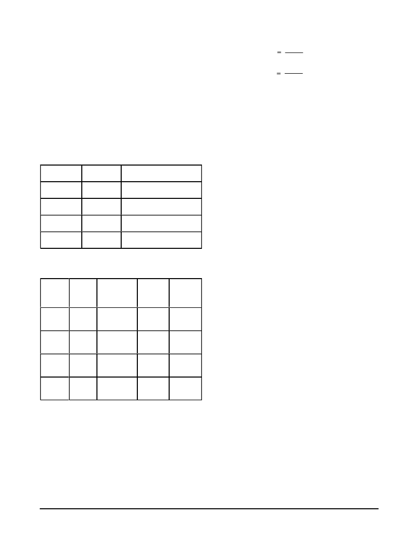
ááááá
ááááááááááááááááá
Bit 6, Reg. 2
ááááá
ááááá
ááááá
Bit 0, Reg. 2
ááááá
ááááá
ááááááááá
ááááá
ááááááááá
Sidetone Switchover Enabled
ááááá
ááááá
ááááááááááááááááá
ááááá
ááááááááá
ááááááááá
No AGC Gain Range, Sidetone
ááááá
0
ááááá
1
ááááááááá
AGC Range of 6.0 dB, only
ááááá
ááááá
1
ááááá
ááááá
0
ááááááááá
ááááááááá
HYS Input Active, HYL Muted
ááááá
ááááááááááááááááá
The ratio between start and stop current for the AGC
curves is programmable for both voltage and current
ááááá
ááááááááá
ááááááááá
áááá
áááá
Bit 4,
‘DC
áááá
áááá
áááá
áááá
áááá
Bit 1,
‘AGC
áááá
áááá
ááááá
ááááá
ááááá
AGC Ratio
Ratio 1:3
áááá
áááá
áááá
áááá
áááá
áááá
áááá
áááá
áááá
áááá
1
ááááá
ááááá
ááááá
Voltage Regu-
Ratio 1:2
áááá
áááá
áááá
21
áááá
áááá
áááá
42
áááá
áááá
áááá
0
áááá
áááá
áááá
0
ááááá
ááááá
ááááá
Current Regu-
lation, AGC
áááá
áááá
áááá
21
áááá
áááá
áááá
42
áááá
áááá
1
áááá
áááá
ááááá
ááááá
lation, AGC
áááá
áááá
áááá
áááá
áááá
áááá
áááá
áááá
áááá
ááááá
ááááá
ááááá
áááá
áááá
áááá
áááá
áááá
áááá
The relation between line current and Istart and Istop is
given by:
RAGC
RS
RAGC
RS
Figures 5, 6, 7 and 8 show the AGC curves for both
voltage regulation and current regulation. In current
regulation, the start point for the AGC curves is coupled to the
knee point of the dc characteristic, or: Iknee = IAGCstart.
Ilinestart
x IAGCstart
Ilinestop
x IAGCstop
LOGIC OUTPUT DRIVERS
The MC34016 is equipped with three logic outputs meant
to interface to the front end of a telephone. The outputs can
be controlled via the serial bus interface. As shown in the
characteristics, the logic outputs are capable of sourcing at
least 1.0 mA and sinking at least 5.0 mA.
Output HKSW
Output HKSW is dedicated to drive the hookswitch. With
HKSW low, the line is opened via Q2 and Q3 and
automatically switches off the line driver transistor Q1. This
feature guarantees fast dc settling after line breaks occurring
during pulse dialing.
Outputs Out1 and Out2
Outputs Out1 and Out2 may be used for any logic function,
such as control of an earth switch and/or a shunt wire.
SERIAL BUS INTERFACE
The serial interface of the MC34016 enables a simple
three wire connection to a micro controller.
Timing
Times t1, t2, t3, t4 and t5 are specified in the electrical
characteristics.
With BEN high, data can be clocked into the serial port by
using Data and Clk lines. On the rising edge of the Clk, the
data enters the MC34016. The last 8–bits of data entered are
shifted into the registers when BEN is forced low. With BEN
low, the serial port of the MC34016 is disabled. BEN must be
kept low until the next register update is needed. Data should
be written by entering the most significant bit first (Bit 7) and
the least significant bit (Bit 0) last.
With BEN low, the Data and Clk lines may be used to
control other devices in the application.
相關PDF資料 |
PDF描述 |
|---|---|
| MC34016P | Battery-Backup Supervisors for RAM Retention 14-TSSOP -40 to 85 |
| MC34017 | Adjustable Battery-Backup Supervisor for RAM Retention 10-MSOP -40 to 85 |
| MC34018 | Adjustable Battery-Backup Supervisor for RAM Retention 10-MSOP -40 to 85 |
| MC34018 | VOICE SWITCHED SPEAKER-PHONE CIRCUIT |
| MC34018DW | VOICE SWITCHED SPEAKERPHONE CIRCUIT |
相關代理商/技術(shù)參數(shù) |
參數(shù)描述 |
|---|---|
| MC34016DWR2 | 制造商:Motorola Inc 功能描述:TELECOM-SLIC, PDSO20 |
| MC34016P | 制造商:MOTOROLA 制造商全稱:Motorola, Inc 功能描述:Cordless Universal Telephone Interface |
| MC34017 | 制造商:MOTOROLA 制造商全稱:Motorola, Inc 功能描述:TELEPHONE TONE RINGER BIPOLAR LINEAR/I2L |
| MC340171D | 制造商:MOT 功能描述:* |
| MC34017A | 制造商:FREESCALE 制造商全稱:Freescale Semiconductor, Inc 功能描述:Telephone Tone Ringer Bipolar Linear/I2L |
發(fā)布緊急采購,3分鐘左右您將得到回復。