- 您現在的位置:買賣IC網 > PDF目錄379308 > MC33030DW (MOTOROLA INC) DC SERVO MOTOR CONTROLLER/DRIVER PDF資料下載
參數資料
| 型號: | MC33030DW |
| 廠商: | MOTOROLA INC |
| 元件分類: | 運動控制電子 |
| 英文描述: | DC SERVO MOTOR CONTROLLER/DRIVER |
| 中文描述: | BRUSH DC MOTOR CONTROLLER, 1 A, PDSO16 |
| 封裝: | PLASTIC, SOP-16 |
| 文件頁數: | 8/16頁 |
| 文件大小: | 322K |
| 代理商: | MC33030DW |
MC33030
8
MOTOROLA ANALOG IC DEVICE DATA
Inverting
Input
Over–Voltage
Monitor
Drive Brake Logic
+
Drive
Output A
14
Drive
Output B
VCC
Motor
10
11
Power
H–Switch
Q Brake
Q Brake
Over–Current
Monitor
Over–Current
Reference
ROC
15
+
16
CDLY
Over–Current
Delay
5.5
μ
A
7.5 V
Ref.
50 k
R
S
Over–
Current
Latch
Q Drive
S
Q Drive
R
Brake Enable
Direction
Latch
18 V
Ref.
Gearbox and Linkage
Gnd
4, 5,12,13
+
Window
Detector
VCC
Reference
Input Filter
20 k
35
μ
A
A
B
3.0 k
3.0 k
35
μ
A
20 k
Non–
Inverting
Input
9
Input
Filter
+
VCC
Output
20 k
0.3 mA
8
20 k
Error Amp
Error Amp
Output Filter/
Feedback
Input
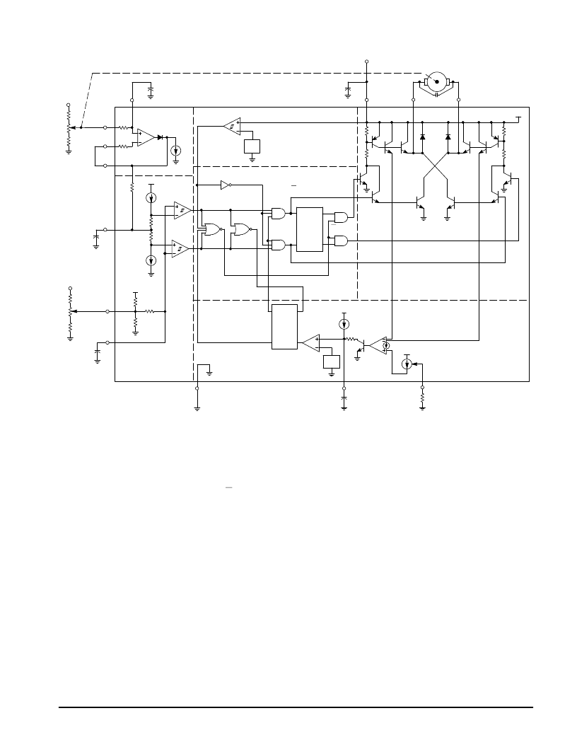
Figure 17. Representative Block Diagram and Typical Servo Application
Q
Q
Q
100 k
2
1
Q
3
6
Reference
Input
7
100 k
If VPin 3 should continue to rise and become greater than V2,
the actuator will have over shot the dead zone range and cause
the motor to run in Direction A until VPin 3 is equal to V3. The
Drive/Brake behavior for Direction A is identical to that of B.
Overshooting the dead zone range in both directions can cause
the servo system to continuously hunt or oscillate. Notice that the
last motor run–direction is stored in the direction latch. This
information is needed to determine whether Q or Q Brake is to be
enabled when VPin 3 enters the dead zone range. The dashed
lines in [8,9] indicate the resulting waveforms of an over–current
condition that has exceeded the programmed time delay. Notice
that both Drive Outputs go into a high impedance state until VPin
2 is readjusted so that VPin 3 enters or crosses through the dead
zone [7, 4].
The inputs of the Error Amp and Window Detector can be
susceptible to the noise created by the brushes of the DC
motor and cause the servo to hunt. Therefore, each of these
inputs are provided with an internal series resistor and are
pinned out for an external bypass capacitor. It has been
found that placing a capacitor with short leadsdirectly across
the brushes will significantly reduce noise problems. Good
quality RF bypass capacitors in the range of 0.001 to 0.1
μ
F
may be required. Many of the more economical motors will
generate significant levels of RF energy over a spectrum that
extends from DC to beyond 200 MHz. The capacitance value
and method of noise filtering must be determined on a
system by system basis.
Thus far, the operating description has been limited to
servo systems in which the motor mechanically drives a
potentiometer for position sensing. Figures 19, 20, 27, and 31
show examples that use light, magnetic flux, temperature,
and pressure as a means to drive the feedback element.
Figures 21, 22 and 23 are examples of two position, open
loop servo systems. In these systems, the motor runs the
actuator to each end of its travel limit where the Over–Current
Monitor detects a locked rotor condition and shuts down the
drive. Figures 32 and 33 show two possible methods of using
the MC33030 as a switching motor controller. In each
example a fixed reference voltage is applied to Pin 2. This
causes Vpin 3 to be less than V4 and Drive Output A, Pin 14,
to be in a low state saturating the TIP42 transistor. In Figure
32, the motor drives a tachometer that generates an ac
voltage proportional to RPM. This voltage is rectified, filtered,
divided down by the speed set potentiometer, and applied to
Pin. 8. The motor will accelerate until VPin 3 is equal to V1 at
which time Pin 14 will go to a high state and terminate the
motor drive. The motor will now coast until VPin 3 is less than
V4 where upon drive is then reapplied. The system operation
of Figure 31 is identical to that of 32 except the signal at Pin
3 is an amplified average of the motors drive and back EMF
voltages. Both systems exhibit excellent control of RPM with
variations of VCC; however, Figure 32 has somewhat better
torque characteristics at low RPM.
相關PDF資料 |
PDF描述 |
|---|---|
| MC33030 | DC SERVO MOTOR CONTROLLER/DRIVER |
| MC33030DW | DC SERVO MOTOR CONTROLLER/DRIVER |
| MC33030P | DC SERVO MOTOR CONTROLLER/DRIVER |
| MC33030P | DC SERVO MOTOR CONTROLLER/DRIVER |
| MC33161 | Tag-it(TM) HF-I Pro Transponder Inlays 24.2-mm Circular 0-RFIDN -25 to 70 |
相關代理商/技術參數 |
參數描述 |
|---|---|
| MC33030DWG | 功能描述:馬達/運動/點火控制器和驅動器 ANA DC SERVO MOT CNTRL RoHS:否 制造商:STMicroelectronics 產品:Stepper Motor Controllers / Drivers 類型:2 Phase Stepper Motor Driver 工作電源電壓:8 V to 45 V 電源電流:0.5 mA 工作溫度:- 25 C to + 125 C 安裝風格:SMD/SMT 封裝 / 箱體:HTSSOP-28 封裝:Tube |
| MC33030DWR2 | 功能描述:馬達/運動/點火控制器和驅動器 DC Brushless Motor RoHS:否 制造商:STMicroelectronics 產品:Stepper Motor Controllers / Drivers 類型:2 Phase Stepper Motor Driver 工作電源電壓:8 V to 45 V 電源電流:0.5 mA 工作溫度:- 25 C to + 125 C 安裝風格:SMD/SMT 封裝 / 箱體:HTSSOP-28 封裝:Tube |
| MC33030DWR2G | 功能描述:馬達/運動/點火控制器和驅動器 DC Brushless Motor Controller RoHS:否 制造商:STMicroelectronics 產品:Stepper Motor Controllers / Drivers 類型:2 Phase Stepper Motor Driver 工作電源電壓:8 V to 45 V 電源電流:0.5 mA 工作溫度:- 25 C to + 125 C 安裝風格:SMD/SMT 封裝 / 箱體:HTSSOP-28 封裝:Tube |
| MC33030P | 功能描述:馬達/運動/點火控制器和驅動器 DC Brushless Motor RoHS:否 制造商:STMicroelectronics 產品:Stepper Motor Controllers / Drivers 類型:2 Phase Stepper Motor Driver 工作電源電壓:8 V to 45 V 電源電流:0.5 mA 工作溫度:- 25 C to + 125 C 安裝風格:SMD/SMT 封裝 / 箱體:HTSSOP-28 封裝:Tube |
| MC33030PG | 功能描述:馬達/運動/點火控制器和驅動器 DC Brushless Motor Controller RoHS:否 制造商:STMicroelectronics 產品:Stepper Motor Controllers / Drivers 類型:2 Phase Stepper Motor Driver 工作電源電壓:8 V to 45 V 電源電流:0.5 mA 工作溫度:- 25 C to + 125 C 安裝風格:SMD/SMT 封裝 / 箱體:HTSSOP-28 封裝:Tube |
發(fā)布緊急采購,3分鐘左右您將得到回復。