- 您現(xiàn)在的位置:買(mǎi)賣(mài)IC網(wǎng) > PDF目錄371019 > MC1670L (MOTOROLA INC) Master-Slave Flip-Flop PDF資料下載
參數(shù)資料
| 型號(hào): | MC1670L |
| 廠商: | MOTOROLA INC |
| 元件分類: | 通用總線功能 |
| 英文描述: | Master-Slave Flip-Flop |
| 中文描述: | 1000 SERIES, POSITIVE EDGE TRIGGERED D FLIP-FLOP, COMPLEMENTARY OUTPUT, CDIP16 |
| 文件頁(yè)數(shù): | 1/4頁(yè) |
| 文件大?。?/td> | 76K |
| 代理商: | MC1670L |

SEMICONDUCTOR TECHNICAL DATA
4–356
REV 5
Motorola, Inc. 1996
3/93
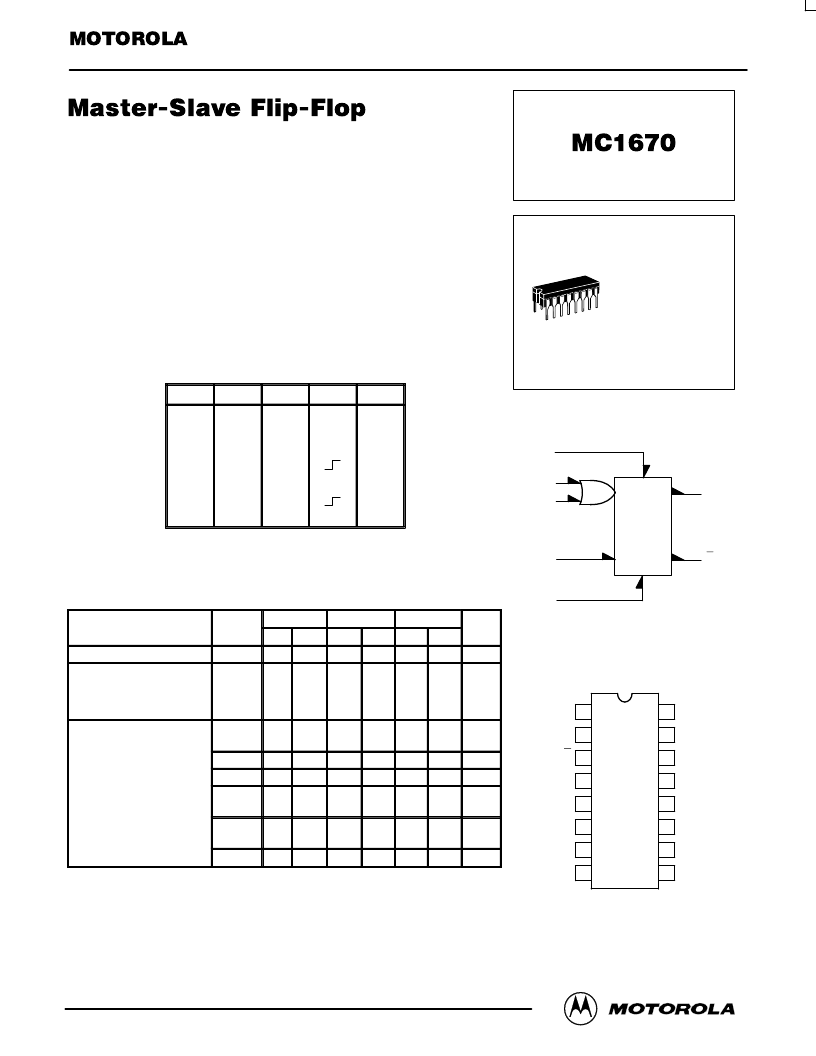
Master slave construction renders the MC1670 relatively insensitive to the
shape of the clock waveform, since only the voltage levels at the clock inputs
control the transfer of information from data input (D) to output.
When both clock inputs (C1 and C2) are in the low state, the data input
affects only the “Master” portion of the flip-flop. The data present in the “Master”
is transferred to the “Slave” when clock inputs (C1 “OR” C2) are taken from a
low to a high level. In other words, the output state of the flip-flop changes on the
positive transition of the clock pulse.
While either C1 “OR” C2 is in the high state, the “Master” (and data input) is
disabled.
Asynchronous Set (S) and Reset (R) override Clock (C) and Data (D) inputs.
Power Dissipation = 220 mW typ (No Load)
fTog = 350 MHz typ
TRUTH TABLE
R
S
D
C
Qn+1
H
L
N.D.
Qn
L
Qn
Qn
H
Qn
L
H
H
L
L
L
L
L
L
H
L
H
L
L
L
L
L
L
X
X
X
L
L
L
H
H
H
X
X
X
L
H
H
L
ND = Not Defined
C = C1 + C2
ELECTRICAL CHARACTERISTICS
Characteristic
Power Supply Drain Current
Input Current
Set, Reset
Clock
Data
Switching Times
Propagation Delay
i i
Symbol
IE
IinH
b l
–30
°
C
Min
—
+25
°
C
Min
—
+85
°
C
Min
—
U i
Unit
mAdc
μ
Adc
Max
—
Max
48
Max
—
—
—
—
—
—
—
—
—
—
550
250
270
—
—
—
—
—
—
tpd
t +
t –
tS“1”
tS“0”
tH“1”
tH“0”
fTog
1.0
0.9
0.5
—
—
2.7
2.7
2.1
—
—
1.1
1.0
0.6
0.4
0.5
2.5
2.5
1.9
—
—
1.1
1.0
0.6
—
—
2.9
2.9
2.3
—
—
ns
Rise Time (10% to 90%)
Fall Time (10% to 90%)
Setup Time
ns
ns
ns
Hold Time
—
—
—
—
0.3
0.5
—
—
—
—
—
—
ns
Toggle Frequency
270
—
300
—
270
—
MHz
LOGIC DIAGRAM
S
C1
C2
D
R
Q
Q
VCC1 = Pin 1
VCC2 = Pin 16
VEE = Pin 8
PIN ASSIGNMENT
1
2
3
4
5
6
7
8
9
10
11
12
13
14
15
16
VCC1
Q
Q
RESET
SET
NC
VEE
VCC2
NC
NC
NC
NC
DATA
NC
CLOCK 2
CLOCK 1
5
7
9
11
4
2
3
L SUFFIX
CERAMIC PACKAGE
CASE 620–10
相關(guān)PDF資料 |
PDF描述 |
|---|---|
| MC1723CG | VOLTAGE REGULATOR |
| MC1723CL | VOLTAGE REGULATOR |
| MC1723G | VOLTAGE REGULATOR |
| MC1723L | VOLTAGE REGULATOR |
| MC1741U | OPERATIONAL AMPLIFIER SILICON MONOLITHIC INTEGRATED CIRCUIT |
相關(guān)代理商/技術(shù)參數(shù) |
參數(shù)描述 |
|---|---|
| MC1671S | 制造商:Motorola Inc 功能描述:1671S |
| MC1672 | 制造商:MOTOROLA 制造商全稱:Motorola, Inc 功能描述:TRIPLE 2-INPUT EXCLUSIVE-OR GATE |
| MC1672F | 制造商:Rochester Electronics LLC 功能描述:- Bulk |
| MC1672L | 制造商:ON Semiconductor 功能描述: |
| MC1674 | 制造商:MOTOROLA 制造商全稱:Motorola, Inc 功能描述:TRIPLE 2-INPUT EXCLUSIVE-NOR GATE |
發(fā)布緊急采購(gòu),3分鐘左右您將得到回復(fù)。