- 您現(xiàn)在的位置:買賣IC網(wǎng) > PDF目錄369894 > MC13110B (Motorola, Inc.) Narrowband FM IF Receiver(窄頻帶FM IF 接收器) PDF資料下載
參數(shù)資料
| 型號: | MC13110B |
| 廠商: | Motorola, Inc. |
| 英文描述: | Narrowband FM IF Receiver(窄頻帶FM IF 接收器) |
| 中文描述: | 窄帶調(diào)頻(窄頻帶調(diào)頻中頻接收器中頻接收機(jī)) |
| 文件頁數(shù): | 2/3頁 |
| 文件大小: | 56K |
| 代理商: | MC13110B |

2
MOTOROLA ANALOG IC APPLICATIONS INFORMATION
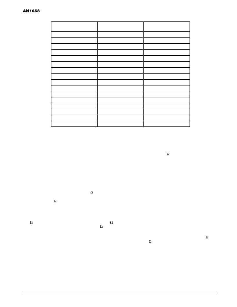
Table 1.
áááááááááááááááááááááá
á
áááááááááááááááááááááá
áááááááááááááááááááááá
áááááááááááááááááááááá
áááááááááááááááááááááá
áááááááááááááááááááááá
áááááááááááááááááááááá
áááááááááááááááááááááá
áááááááááááááááááááááá
áááááááááááááááááááááá
áááááááááááááááááááááá
áááááááááááááááááááááá
áááááááááááááááááááááá
ááááááá
Capacitor Select Number
á
Capacitor Value (pF)
ááááááá
á
Capacitor Value (pF)
áááááá
á
áááááááááááááááááááááá
2
0.8
0.6
áááááááááááááááááááááá
4
5.7
6.0
áááááááááááááááááááááá
7
7.9
4.9
áááááááááááááááááááááá
9
–
9.4
áááááááááááááááááááááá
14
–
14.9
FIRST MIXER
The first mixer of the MC13110A,B/13111A,B has
improved performance for conversion gain, 1.0 dB
compression and IP3 level over the MC13110/13111. In
addition, the MC13110A,B/13111A,B has a programmable
“IP3 increase” bit, which further improves the 1.0 dB
compression point and IP3 level. As a result, no
modifications should be required to the first mixer with
respect to these parameters, regardless of the setting of the
IP3 increase bit.
The first mixer differential input impedance for both the
MC13110/13111 and MC13110/13111 remain essentially the
same. However, the single ended impedance of the
MC13110/13111 is now approximately 1600 || 3.7 pF, while
the single ended input impedance of the MC13110/13111 is
approximately 800
|| 3.2 pF. As a result, single–ended
mixer driving applications may require some modifications to
insure optimum impedance matching.
The output impedance of the first mixer for the
MC13110A,B/13111A,B has decreased to approximately
300 || 3.7 pF as compared to the MC13110/13111 395 ||
3.2 pF. For most applications using a external, 330 ceramic
bandpass filter, no modifications should be necessary (due to
the relatively wide bandwidth of the ceramic element). For
applications that use a crystal filter, these changes become
important. However, since most crystal applications use an
external resistor to match the impedance, the only change
which should be required would be the value of the external
resistor itself.
SECOND MIXER
The second mixer of the MC13110A,B/13111A,B has
significantly improved performance for conversion gain,
1.0 dB compression and IP3 level over the MC13110/13111.
As a result, no modifications should be required to the
second mixer with respect to these parameters, regardless of
the setting of the IP3 increase bit.
The second mixer input impedance for both the
MC13110/13111 and MC13110/13111 remain essentially the
same (approximately 2850 || 3.6 pF), and no modifications
(for ceramic or crystal bandpass filters) should be required.
Additionally, the second mixer output impedance for both the
MC13110/13111 and MC13110A,B/13111A,B are not
changed, so no modifications should be required for the
second bandpass filter.
IF AMPLIFIER, LIMITER, RSSI, DETECTOR, and
RECEIVE AUDIO
The
receive
gain
MC13110A,B/13111A,B is from –9.0 dB to 10 dB, while the
MC13110/13111 range is from –15 dB to 16 dB. Since the
registers are compatible, this should not pose any significant
problems. The reduced range has proved to be adequate for
normal applications.
The remainder of these sections remain essentially
unchanged and no external modifications should be required.
adjust
range
for
the
DATA AMPLIFIER
The data amplifier input impedance of the
MC13110A,B/13111A,B has been increased to 240 k (from
a nominal 11 k for the MC13110/13111), making it much
easier to implement an external bandpass filter. For most
applications, this increased input impedance should not
require modifications.
TRANSMIT AUDIO PATH
The maximum output swing capability of the
MC13110A,B/13111A,B is about 4.0 dB less than the
MC13110/13111. For most applications, this is more than
sufficient to drive an external transmit VCO. If this does
相關(guān)PDF資料 |
PDF描述 |
|---|---|
| MC13111 | Narrowband FM IF Receiver(窄頻帶FM IF 接收器) |
| MC13135 | FM Communications Receivers(FM通信接收器) |
| MC13155 | Wideband FM IF Detector(寬頻帶FM IF探測器) |
| MC13155D | WIDEBAND FM IF |
| MC13156 | Wideband FM IF System |
相關(guān)代理商/技術(shù)參數(shù) |
參數(shù)描述 |
|---|---|
| MC13110BFB | 制造商:MOTOROLA 制造商全稱:Motorola, Inc 功能描述:UNIVERSAL NARROWBAND FM RECEIVER INTEGRATED CIRCUIT |
| MC13110BFTA | 制造商:Motorola 功能描述:MOTOROLA 9942 |
| MC13111AFB | 制造商:MOTOROLA 制造商全稱:Motorola, Inc 功能描述:UNIVERSAL NARROWBAND FM RECEIVER INTEGRATED CIRCUIT |
| MC13111AFTA | 制造商:MOTOROLA 制造商全稱:Motorola, Inc 功能描述:UNIVERSAL CORDLESS TELEPHONE SUBSYSTEM IC |
| MC13111BFB | 制造商:MOTOROLA 制造商全稱:Motorola, Inc 功能描述:UNIVERSAL NARROWBAND FM RECEIVER INTEGRATED CIRCUIT |
發(fā)布緊急采購,3分鐘左右您將得到回復(fù)。