- 您現(xiàn)在的位置:買賣IC網(wǎng) > PDF目錄69024 > MC12430FA (INTEGRATED DEVICE TECHNOLOGY INC) 800 MHz, OTHER CLOCK GENERATOR, PQFP32 PDF資料下載
參數(shù)資料
| 型號: | MC12430FA |
| 廠商: | INTEGRATED DEVICE TECHNOLOGY INC |
| 元件分類: | 時鐘產(chǎn)生/分配 |
| 英文描述: | 800 MHz, OTHER CLOCK GENERATOR, PQFP32 |
| 封裝: | PLASTIC, LQFP-32 |
| 文件頁數(shù): | 7/12頁 |
| 文件大小: | 503K |
| 代理商: | MC12430FA |
MC12430
4
MOTOROLA
9-BIT SR
2-BIT SR
3-BIT SR
DIV 16
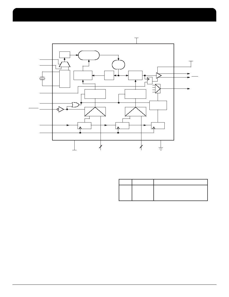
Figure 3. MC12430 Block Diagram (28–Lead PLCC Pinout)
16MHz
S_LOAD
P_LOAD
S_DATA
S_CLOCK
XTAL1
XTAL2
OSC
4
5
PHASE
DETECTOR
28
7
9-BIT DIV M
COUNTER
LATCH
VCO
DIV N
(1, 2, 4, 8)
LATCH
400-800
MHz
FOUT
+3.3 or 5.0V
25
24
23
VCCO
LATCH
TEST
20
+3.3 or 5.0V
PLL_VCC
1MHz
FREF
01
27
26
01
VCC1
+3.3 or 5.0V
M[8:0]
9
8:16
N[1:0]
2
17, 18
21
22, 19
OE
6
FREF_EXT
2
XTAL_SEL
3
DIV 2
200-400
MHz
PROGRAMMING INTERFACE
Programming the device amounts to properly configuring
the internal dividers to produce the desired frequency at the
outputs. The output frequency can by represented by this
formula:
FOUT = (FXTAL ÷ 16) x M x 2 ÷ N
(1)
Where FXTAL is the crystal frequency, M is the loop divider
modulus, and N is the output divider modulus. Note that it is
possible to select values of M such that the PLL is unable to
achieve loop lock. To avoid this, always make sure that M is
selected to be 200
≤ M ≤ 400 for any input reference.
Assuming that a 16 MHz reference frequency is used, the
above equation reduces to:
FOUT = 2 x M
÷ N
Substituting the four values for N (1, 2, 4, 8) yields:
Output Frequency Range
N
FOUT
OUTPUT FREQUENCY RANGE
1
2
4
8
2 x M
M
÷ 2
M
÷ 4
400 – 800 MHZ
200 – 400 MHZ
100 – 200 MHZ
50 – 100 MHZ
From these ranges, the user will establish the value of N
required, then the value of M can be calculated based on the
appropriate equation above. For example, if an output
frequency of 131 MHz was desired, the following steps would
be taken to identify the appropriate M and N values. 131MHz
falls within the frequency range set by an N value of 4 so N
[1:0] = 01. For N = 4, FOUT = M
÷ 2 and M = 2 x FOUT.
Therefore, M = 131 x 2 = 262, so M[8:0] = 100000110.
Following this same procedure, a user can generate any
whole frequency desired between 50 and 800MHz. Note that
for N > 2 fractional values of FOUT can be realized. The size of
the programmable frequency steps (and thus the indicator of
the fractional output frequencies achievable) will be equal to
FXTAL
÷ 8 ÷ N.
For input reference frequencies other than 16 MHz, the set
of appropriate equations can be deduced from equation 1. For
computer applications, another useful frequency base would
F
re
e
sc
a
le
S
e
m
ic
o
n
d
u
c
to
r,
I
Freescale Semiconductor, Inc.
For More Information On This Product,
Go to: www.freescale.com
n
c
..
.
MC12430
High Frequency Clock Synthesizer
NETCOM
IDT High Frequency Clock Synthesizer
Freescale Timing Solutions Organization has been acquired by Integrated Device Technology, Inc
MC12430
4
相關PDF資料 |
PDF描述 |
|---|---|
| MC13214R2 | SPECIALTY MICROPROCESSOR CIRCUIT, BGA71 |
| MC13224VR2 | SPECIALTY MICROPROCESSOR CIRCUIT, PBGA99 |
| MC13226V | SPECIALTY MICROPROCESSOR CIRCUIT, PBGA99 |
| MC13226VR2 | SPECIALTY MICROPROCESSOR CIRCUIT, PBGA99 |
| MC13224V | SPECIALTY MICROPROCESSOR CIRCUIT, PBGA99 |
相關代理商/技術參數(shù) |
參數(shù)描述 |
|---|---|
| MC12430FN | 制造商:MOTOROLA 制造商全稱:Motorola, Inc 功能描述:HIGH FREQUENCY PLL CLOCK GENERATOR |
| MC12439 | 制造商:MOTOROLA 制造商全稱:Motorola, Inc 功能描述:HIGH FREQUENCY PLL CLOCK GENERATOR |
| MC12439FN | 制造商:Motorola Inc 功能描述: 制造商:Motorola Inc 功能描述:MISCELLANEOUS CLOCK GENERATOR, 28 Pin, Plastic, PLCC |
| MC1243F | 制造商:Rochester Electronics LLC 功能描述:- Bulk |
| MC1245L | 制造商:Rochester Electronics LLC 功能描述:- Bulk |
發(fā)布緊急采購,3分鐘左右您將得到回復。