- 您現(xiàn)在的位置:買賣IC網(wǎng) > PDF目錄376150 > MBRF2045CT (GE Security, Inc.) Schottky Isolated Plastic Rectifier(肖特基隔離塑膠整流器) PDF資料下載
參數(shù)資料
| 型號(hào): | MBRF2045CT |
| 廠商: | GE Security, Inc. |
| 英文描述: | Schottky Isolated Plastic Rectifier(肖特基隔離塑膠整流器) |
| 中文描述: | 肖特基整流器的隔離塑料(肖特基隔離塑膠整流器) |
| 文件頁數(shù): | 1/2頁 |
| 文件大小: | 124K |
| 代理商: | MBRF2045CT |
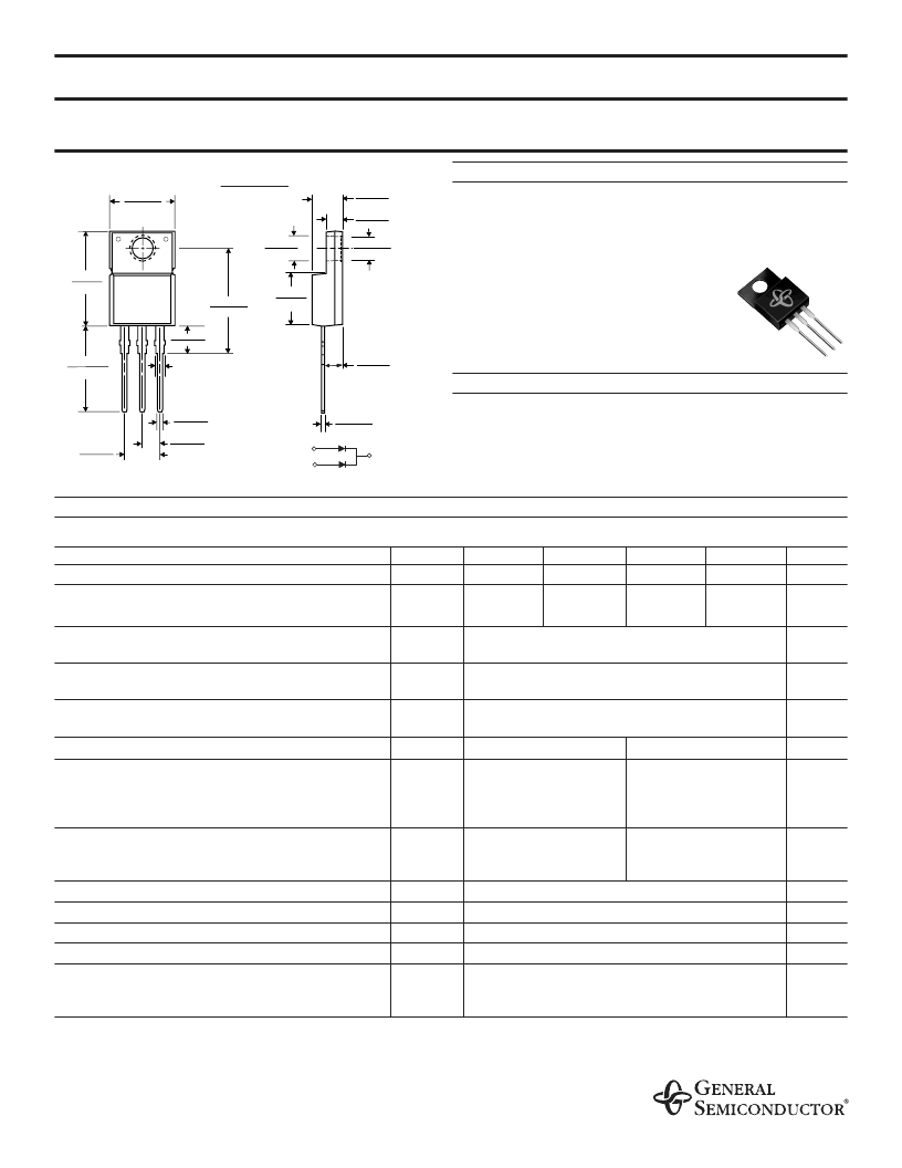
MBRF2035CT THRU MBRF2060CT
SCHOTTKY ISOLATED PLASTIC RECTIFIER
Reverse Voltage -
35 to 60 Volts
Forward Current -
20.0 Amperes
FEATURES
¨
Isolated plastic package has Underwriters Laboratory
Flammability Classification 94V-0
¨
Dual rectifier construction, positive center tap
¨
Metal silicon junction,majority carrier conduction
¨
Low power loss, high efficiency
¨
High current capability, low forward voltage drop
¨
High surge capability
¨
Guardring for overvoltage protection
¨
For use in low voltage, high frequency inverters,
free wheeling, and polarity protection applications
¨
High temperature soldering guaranteed:
250
°
C/10 seconds, 0.25" (6.35mm) from case
MECHANICAL DATA
Case:
ITO-220AB fully overmolded plastic body
Terminals:
Leads solderable per MIL-STD-750,Method 2026
Polarity:
As marked
Mounting Position:
Any
Weight:
0.08 ounce, 2.24 grams
Mounting Torque:
5 in. - lbs.max.
MAXIMUM RATINGS AND ELECTRICAL CHARACTERISTICS
Ratings at 25C ambient temperature unless otherwise specified.
SYMBOLS
MBRF2035CT
MBRF2045CT
MBRF2050CT
MBRF2060CT
UNITS
Maximum repetitive peak reverse voltage
V
RRM
35
45
50
60
Volts
Maximum working peak reverse voltage
V
RWM
35
45
50
60
Volts
Maximum DC blocking voltage
V
DC
35
45
50
60
Volts
Maximum average forward rectified current
at T
C
=135C
I
(AV)
20.0
Amps
Peak repetitive forward current per leg at T
C
=135C
(rated V
R
, sq. wave 2.0 KH
Z
)
I
FRM
20.0
Amps
Peak forward surge current 8.3ms single half sine-
wave superimposed on rated load (JEDEC Method)
I
FSM
150.0
Amps
Peak repetitive reverse surge current
(NOTE 1)
I
RRM
1.0
_
0.5
Amps
Maximum instantaneous
forward voltage per leg at
I
F
=10A, T
C
=25C
I
F
=10A, T
C
=125C
I
F
=20A, T
C
=25C
I
F
=20A, T
C
=125C
0.80
0.70
0.95
0.85
V
F
0.57
0.84
0.72
Volts
(NOTE 2)
Maximum instantaneous reverse current at
rated DC blocking voltage per leg
T
C
=25C
T
C
=125C
I
R
0.1
15.0
0.15
150.0
mA
Voltage rate of change, (rated V
R
)
dv/dt
10,000
V/
m
s
C/W
Typical thermal resistance per leg
(NOTE 3
)
R
Q
JC
T
J
5.0
Operating junction temperature range
-65 to +150
C
Storage temperature range
T
STG
-65 to +175
C
RMS Isolation voltage from terminals to heatsink
with RH 2 30%
4500
(NOTE 4)
3500
(NOTE 5)
1500
(NOTE 6)
V
ISOL
Volts
NOTES:
(1) 2.0
m
s pulse width, f=1.0KH
Z
(2) Pulse test: 300
m
s pulse width, 1% duty cycle
(3) Thermal resistance from junction to case per leg
(4) Clip mounting (on case), where lead does not overlap heatsink with 0.110ó offset.
(5) Clip mounting (on case, where leads do overlap heatsink.
(6) Screw mounting with 4-40 screw, where washer diameter is
£
4.9 mm (0.19ó).
2/18/99
Dimensions in inches and (millimeters)
NEW PRODUCT
NEW PRODUCT
NEW PRODUCT
0.060 (1.52)
0.405 (10.27)
0.383 (9.72)
0.676 (17.2)
0.646 (16.4)
0.191 (4.85)
0.171 (4.35)
0.600 (15.5)
0.580 (14.5)
0.560 (14.22)
0.530 (13.46)
0.037 (0.94)
0.027 (0.69)
0.140 (3.56)
0.130 (3.30)
0.350 (8.89)
0.330 (8.38)
0.188 (4.77)
0.172 (4.36)
0.110 (2.80)
0.100 (2.54)
0.131 (3.39)
0.122 (3.08)
0.110 (2.80)
0.100 (2.54)
0.022 (0.55)
0.014 (0.36)
0.105 (2.67)
0.095 (2.41)
0.205 (5.20)
0.195 (4.95)
PIN 1
PIN 3
PIN 2
1
3
PIN
2
DIA.
DIA.
ITO-220AB
相關(guān)PDF資料 |
PDF描述 |
|---|---|
| MBRF2050CT | Schottky Isolated Plastic Rectifier(肖特基隔離塑膠整流器) |
| MBRF2060CT | Schottky Isolated Plastic Rectifier(肖特基隔離塑膠整流器) |
| MBRF2535CT | Schottky Isolated Plastic package Rectifier(肖特基絕緣塑料封裝整流器) |
| MBRF2550CT | Schottky Isolated Plastic package Rectifier(肖特基絕緣塑料封裝整流器) |
| MBRF2560CT | Schottky Isolated Plastic package Rectifier(肖特基絕緣塑料封裝整流器) |
相關(guān)代理商/技術(shù)參數(shù) |
參數(shù)描述 |
|---|---|
| MBRF2045CT-45 | 制造商:KERSEMI 制造商全稱:Kersemi Electronic Co., Ltd. 功能描述:Guardring for overvoltage protection |
| MBRF2045CT-E3 | 制造商:KERSEMI 制造商全稱:Kersemi Electronic Co., Ltd. 功能描述:Guardring for overvoltage protection |
| MBRF2045CT-E3/45 | 功能描述:肖特基二極管與整流器 45 Volt 20A Dual Common-Cathode RoHS:否 制造商:Skyworks Solutions, Inc. 產(chǎn)品:Schottky Diodes 峰值反向電壓:2 V 正向連續(xù)電流:50 mA 最大浪涌電流: 配置:Crossover Quad 恢復(fù)時(shí)間: 正向電壓下降:370 mV 最大反向漏泄電流: 最大功率耗散:75 mW 工作溫度范圍:- 65 C to + 150 C 安裝風(fēng)格:SMD/SMT 封裝 / 箱體:SOT-143 封裝:Reel |
| MBRF2045CT-E345 | 制造商:KERSEMI 制造商全稱:Kersemi Electronic Co., Ltd. 功能描述:Guardring for overvoltage protection |
| MBRF2045CTG | 功能描述:肖特基二極管與整流器 20A 45V RECTIFIER RoHS:否 制造商:Skyworks Solutions, Inc. 產(chǎn)品:Schottky Diodes 峰值反向電壓:2 V 正向連續(xù)電流:50 mA 最大浪涌電流: 配置:Crossover Quad 恢復(fù)時(shí)間: 正向電壓下降:370 mV 最大反向漏泄電流: 最大功率耗散:75 mW 工作溫度范圍:- 65 C to + 150 C 安裝風(fēng)格:SMD/SMT 封裝 / 箱體:SOT-143 封裝:Reel |
發(fā)布緊急采購,3分鐘左右您將得到回復(fù)。