- 您現(xiàn)在的位置:買賣IC網(wǎng) > PDF目錄383549 > MAX9982EVKIT (Maxim Integrated Products, Inc.) Evaluation Kit for the MAX9982 PDF資料下載
參數(shù)資料
| 型號: | MAX9982EVKIT |
| 廠商: | Maxim Integrated Products, Inc. |
| 英文描述: | Evaluation Kit for the MAX9982 |
| 中文描述: | MAX9982評估板 |
| 文件頁數(shù): | 2/8頁 |
| 文件大小: | 315K |
| 代理商: | MAX9982EVKIT |
E
MAX9981 Evaluation Kit
2
_______________________________________________________________________________________
Quick Start
The MAX9981 EV kit is fully assembled and factory test-
ed. Follow the instructions in the
Connections and
Setup
section for proper device evaluation.
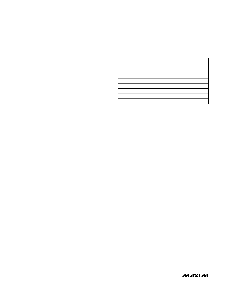
Test Equipment Required
Table 1 lists the equipment required to verify the opera-
tion of the MAX9981 EV kit. It is intended as a guide
only, and some substitutions can be made.
Connections and Setup
This section provides a step-by-step guide for testing
the basic functionality of the EV kit. As a general pre-
caution to prevent damaging the outputs by driving
high-VSWR loads,
do not turn on DC power or RF
signals until all connections are made.
This procedure is specific to operation with an RF input
frequency range of 825MHz to 915MHz, low-side injected
LO for a 100MHz IF. Choose the test frequency based on
the particular system
’
s frequency plan, and adjust the
following procedure accordingly. See Figure 1 for the
main mixer test setup diagram.
1) Calibrate the power meter for 870MHz. For safety
margin, use a power sensor rated to at least
+20dBm, or use padding to protect the power head
as necessary.
2) Connect 3dB pads to DUT ends of each of the
three RF signal generators
’
SMA cables. This
padding improves VSWR and reduces the errors
due to mismatch.
3) Use the power meter to set the RF signal genera-
tors according to the following:
RFMAIN signal source: -5dBm into DUT at
870MHz (approximately -2dBm before the 3dB
pad)
LO1 signal source: 0dBm into DUT at 770MHz
(approximately +3dBm before the 3dB pad)
LO2 signal source: 0dBm into DUT at 771MHz
(approximately +3dBm before the 3dB pad)
4) Disable the signal generator outputs.
5) Connect the RF source (with pad) to RFMAIN.
6) Connect the LO1 and LO2 signal sources to the EV
kit LO inputs.
7) Measure loss in the 3dB pad and the cable that is
connected to IFMAIN. Losses are frequency
dependent, so test this at 100MHz (IF frequency).
Use this loss as an offset in all output power/gain
calculations.
8) Connect this 3dB pad to the EV kit
’
s IFMAIN con-
nector, and connect a cable from the pad to the
spectrum analyzer.
9) Connect a 50
terminator to the unused RF input
and IF output.
10) Set the DC supply to +5.0V, and set a current limit to
around 500mA if possible. Disable the output voltage
and connect supply to the EV kit through a low inter-
nal resistance ammeter. Enable the supply. Re-adjust
the supply to get +5.0V at the EV kit since there will
be a voltage drop across the ammeter when the
mixer is drawing current.
11) Select LO1 by leaving LOSEL (TP3) unconnected
or connecting it to +5V. If left floating, LOSEL will
be pulled high by an on-board pullup resistor.
12) Enable the LO and the RF sources.
To test the diversity mixer, disable the LO and RF
sources, turn off the DC supply and repeat steps 3
through 12, replacing RFDIV for RFMAIN and IFDIV for
IFMAIN. Be sure to terminate RFMAIN and IFMAIN with
50
terminators. See Figure 2 for diversity mixer test
setup.
Testing the Mixer
Adjust the center and span of the spectrum analyzer to
observe the IF output tone at 100MHz. The level should
be about -5.4dBm (2.6dB conversion gain, 3dB pad
loss). The spectrum analyzer
’
s absolute magnitude
accuracy is typically no better than ±1dB; therefore,
use the power meter to get an accurate output power
measurement. There will also be a tone at 99MHz which
is due to the LO signal applied to LO2. The amount of
suppression between the 100MHz and 99MHz signals
is the switch isolation.
Connect LOSEL to GND to select LO2. Observe that
the IF output level at 99MHz increases while the
100MHz level decreases.
EQUIPMENT
HP E3631A
Fluke 75 series II
HP/Agilent 8648B
HP 437B
HP 8561
HP 8482A
3dB pad
50
termination
QTY
1
1
3
1
1
1
4
2
DESCRIPTION
DC power supply
Digital multimeter (ammeter)
RF signal generators
RF power meter
Spectrum analyzer
High-power sensor (power head)
3dB attenuators
50
(1W) terminations
Table 1. Test Equipment Required
相關(guān)PDF資料 |
PDF描述 |
|---|---|
| MAX9987 | +14dBm to +20dBm LO Buffers/Splitters with ±.1dB Variation |
| MAX9987EVKIT | Evaluation Kits for the MAX9987/MAX9988 |
| MAX9988 | +14dBm to +20dBm LO Buffers/Splitters with ±.1dB Variation |
| MAX9988EVKIT | Evaluation Kits for the MAX9987/MAX9988 |
| MAX9989 | +14dBm to +20dBm LO Buffers with ±.1dB Variation |
相關(guān)代理商/技術(shù)參數(shù) |
參數(shù)描述 |
|---|---|
| MAX9984ETP | 功能描述:上下轉(zhuǎn)換器 RoHS:否 制造商:Texas Instruments 產(chǎn)品:Down Converters 射頻:52 MHz to 78 MHz 中頻:300 MHz LO頻率: 功率增益: P1dB: 工作電源電壓:1.8 V, 3.3 V 工作電源電流:120 mA 最大功率耗散:1 W 最大工作溫度:+ 85 C 安裝風(fēng)格:SMD/SMT 封裝 / 箱體:PQFP-128 |
| MAX9984ETP+ | 功能描述:上下轉(zhuǎn)換器 SiGe 400-1000MHz Downconversion Mixer RoHS:否 制造商:Texas Instruments 產(chǎn)品:Down Converters 射頻:52 MHz to 78 MHz 中頻:300 MHz LO頻率: 功率增益: P1dB: 工作電源電壓:1.8 V, 3.3 V 工作電源電流:120 mA 最大功率耗散:1 W 最大工作溫度:+ 85 C 安裝風(fēng)格:SMD/SMT 封裝 / 箱體:PQFP-128 |
| MAX9984ETP+D | 制造商:Maxim Integrated Products 功能描述:UP/DOWN CONV MIXER 5V 1GHZ 20TQFN EP - Rail/Tube |
| MAX9984ETP+T | 功能描述:上下轉(zhuǎn)換器 SiGe 400-1000MHz Downconversion Mixer RoHS:否 制造商:Texas Instruments 產(chǎn)品:Down Converters 射頻:52 MHz to 78 MHz 中頻:300 MHz LO頻率: 功率增益: P1dB: 工作電源電壓:1.8 V, 3.3 V 工作電源電流:120 mA 最大功率耗散:1 W 最大工作溫度:+ 85 C 安裝風(fēng)格:SMD/SMT 封裝 / 箱體:PQFP-128 |
| MAX9984ETP+TD | 制造商:Maxim Integrated Products 功能描述:UP/DOWN CONV MIXER 5V 1GHZ 20TQFN EP - Tape and Reel |
發(fā)布緊急采購,3分鐘左右您將得到回復(fù)。