- 您現(xiàn)在的位置:買賣IC網(wǎng) > PDF目錄11687 > MAX9271GTJ+ (Maxim Integrated Products)IC SERIALIZER 16BIT GMSL 32TQFN PDF資料下載
參數(shù)資料
| 型號: | MAX9271GTJ+ |
| 廠商: | Maxim Integrated Products |
| 文件頁數(shù): | 16/49頁 |
| 文件大?。?/td> | 0K |
| 描述: | IC SERIALIZER 16BIT GMSL 32TQFN |
| 標準包裝: | 60 |
| 系列: | * |
第1頁第2頁第3頁第4頁第5頁第6頁第7頁第8頁第9頁第10頁第11頁第12頁第13頁第14頁第15頁當前第16頁第17頁第18頁第19頁第20頁第21頁第22頁第23頁第24頁第25頁第26頁第27頁第28頁第29頁第30頁第31頁第32頁第33頁第34頁第35頁第36頁第37頁第38頁第39頁第40頁第41頁第42頁第43頁第44頁第45頁第46頁第47頁第48頁第49頁
MAX9271
16-Bit GMSL Serializer with Coax or
STP Cable Drive
23
Maxim Integrated
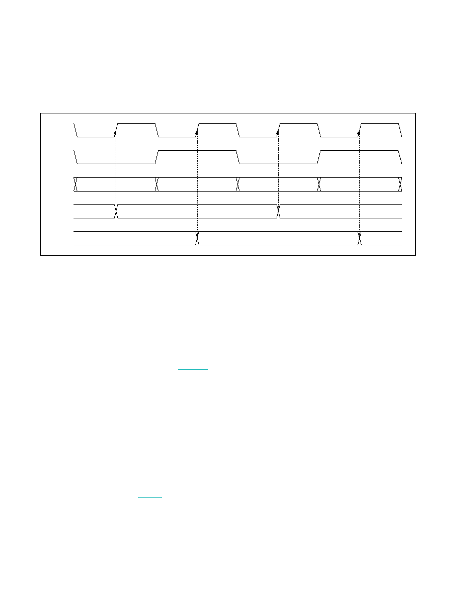
Figure 16. Double-Input Waveform (Latch on Rising Edge of PCLKIN Selected)
Serial Link Signaling and Data Format
The serializer uses differential CML signaling to drive
twisted-pair cable and single-ended CML to drive coax
cable. The output amplitude is programmable.
Input data is scrambled and then 8b/10b coded. The
deserializer recovers the embedded serial clock, then
samples, decodes, and descrambles the data. In 24-bit
or 32-bit mode, 22 or 30 bits contain the video data
and/or error-correction bits, if used. The 23rd or 31st bit
carries the forward control-channel data. The last bit is
the parity bit of the previous 23 or 31 bits. (Figure 17).
Reverse Control Channel
The serializer uses the reverse control channel to receive
I2C/UART and GPO signals from the deserializer in the
opposite direction of the video stream. The reverse
control channel and forward video data coexist on the
same serial cable, forming a bidirectional link. The
reverse control channel operates independently from the
forward control channel. The reverse control channel is
available 2ms after power-up. The serializer temporarily
disables the reverse control channel for 350Fs after start-
ing/stopping the forward serial link.
Data-Rate Selection
The serializer/deserializer use DRS, DBL, and BWS to set
the PCLKIN frequency range (Table 3). Set DRS = 1 for
a PCLKIN frequency range of 6.25MHz to 12.5MHz (32-
bit, single-input mode) or 8.33MHz to 16.66MHz (24-bit,
single-input mode). Set DRS = 0 for normal operation.
It is not recommended to use double-input mode when
DRS = 1.
Control Channel and Register
Programming
The control channel is available for the FC to send and
receive control data over the serial link simultaneously
with the high-speed data. The FC controls the link from
either the serializer or the deserializer side. The control
channel between the FC and serializer or deserializer
runs in base mode or bypass mode, according to the
mode selection (MS/HVEN) input of the device connected
to the FC. Base mode is a half-duplex control channel and
bypass mode is a full-duplex control channel.
UART Interface
In base mode, the FC is the host and can access the
registers of both the serializer and deserializer from
either side of the link using the GMSL UART protocol.
The FC can also program the peripherals on the remote
side by sending the UART packets to the serializer or
deserializer, with the UART packets converted to I2C
by the device on the remote side of the link. The FC
communicates with a UART peripheral in base mode
(through INTTYPE register settings), using the half-duplex
default GMSL UART protocol of the serializer/deserial-
izer. The device addresses of the serializer/deserializer in
base mode are programmable. The default value is 0x80
for the serializer and 0x90 for the deserializer.
When the peripheral interface is I2C, the serializer/
deserializer convert UART packets to I2C that have
device addresses different from those of the serializer or
deserializer. The converted I2C bit rate is the same as the
original UART bit rate.
FIRST WORD
SECOND WORD
THIRD WORD
FOURTH WORD
FIRST WORD
THIRD WORD
FIRST AND SECOND WORD
THIRD AND FOURTH WORD
PCLKIN
÷ 2
LATCH A
LATCH B
DIN0–DIN14
OR
DIN0–DIN10
相關PDF資料 |
PDF描述 |
|---|---|
| MAX9218ETM+T | IC DESERIALIZER LVDS 48-TQFN |
| MAX9250ECM+T | IC DESERIALIZER LVDS 48-LQFP |
| MAX9260GCB/V+T | IC DESERIALIZER GMSL 64TQFP |
| MAX9259GCB/V+T | IC SERIALIZER GMSL 64TQFP |
| MAX9217ETM+T | IC SERIALIZER LVDS 48-TQFN |
相關代理商/技術參數(shù) |
參數(shù)描述 |
|---|---|
| MAX9271GTJ/V+ | 功能描述:串行器/解串器 - Serdes 1.5Gbps 16-bit Coax/STP serializer RoHS:否 制造商:Texas Instruments 類型:Deserializer 數(shù)據(jù)速率:1.485 Gbit/s 輸入類型:ECL/LVDS 輸出類型:LVCMOS 輸入端數(shù)量:1 輸出端數(shù)量:20 工作電源電壓:2.375 V to 2.625 V 工作溫度范圍:0 C to + 70 C 封裝 / 箱體:TQFP-64 |
| MAX9271GTJ/V+T | 功能描述:串行器/解串器 - Serdes 1.5Gbps 16-bit Coax/STP serializer RoHS:否 制造商:Texas Instruments 類型:Deserializer 數(shù)據(jù)速率:1.485 Gbit/s 輸入類型:ECL/LVDS 輸出類型:LVCMOS 輸入端數(shù)量:1 輸出端數(shù)量:20 工作電源電壓:2.375 V to 2.625 V 工作溫度范圍:0 C to + 70 C 封裝 / 箱體:TQFP-64 |
| MAX9271GTJ+ | 功能描述:串行器/解串器 - Serdes 1.5Gbps 16-bit Coax/STP serializer RoHS:否 制造商:Texas Instruments 類型:Deserializer 數(shù)據(jù)速率:1.485 Gbit/s 輸入類型:ECL/LVDS 輸出類型:LVCMOS 輸入端數(shù)量:1 輸出端數(shù)量:20 工作電源電壓:2.375 V to 2.625 V 工作溫度范圍:0 C to + 70 C 封裝 / 箱體:TQFP-64 |
| MAX9271GTJ+T | 功能描述:串行器/解串器 - Serdes 1.5Gbps 16Bit Coax/STP serializer RoHS:否 制造商:Texas Instruments 類型:Deserializer 數(shù)據(jù)速率:1.485 Gbit/s 輸入類型:ECL/LVDS 輸出類型:LVCMOS 輸入端數(shù)量:1 輸出端數(shù)量:20 工作電源電壓:2.375 V to 2.625 V 工作溫度范圍:0 C to + 70 C 封裝 / 箱體:TQFP-64 |
| MAX9272 | 制造商:MAXIM 制造商全稱:Maxim Integrated Products 功能描述:28-Bit GMSL Deserializer for Coax or STP Cable |
發(fā)布緊急采購,3分鐘左右您將得到回復。