- 您現(xiàn)在的位置:買賣IC網(wǎng) > PDF目錄11582 > MAX5945CAX+ (Maxim Integrated Products)IC NETWORK PWR CTRL 36-SSOP PDF資料下載
參數(shù)資料
| 型號: | MAX5945CAX+ |
| 廠商: | Maxim Integrated Products |
| 文件頁數(shù): | 15/44頁 |
| 文件大?。?/td> | 0K |
| 描述: | IC NETWORK PWR CTRL 36-SSOP |
| 產(chǎn)品培訓(xùn)模塊: | Lead (SnPb) Finish for COTS Obsolescence Mitigation Program |
| 標準包裝: | 30 |
| 控制器類型: | 網(wǎng)絡(luò)電源控制器 |
| 接口: | I²C |
| 電源電壓: | 3.3V |
| 電流 - 電源: | 4.2mA |
| 工作溫度: | 0°C ~ 70°C |
| 安裝類型: | 表面貼裝 |
| 封裝/外殼: | 36-BSOP(0.295",7.50mm 寬) |
| 供應(yīng)商設(shè)備封裝: | 36-SSOP |
| 包裝: | 管件 |
第1頁第2頁第3頁第4頁第5頁第6頁第7頁第8頁第9頁第10頁第11頁第12頁第13頁第14頁當(dāng)前第15頁第16頁第17頁第18頁第19頁第20頁第21頁第22頁第23頁第24頁第25頁第26頁第27頁第28頁第29頁第30頁第31頁第32頁第33頁第34頁第35頁第36頁第37頁第38頁第39頁第40頁第41頁第42頁第43頁第44頁
MAX5945
Message Format for Reading
The MAX5945 reads using the MAX5945’s internally
stored command byte as an address pointer, the same
way the stored command byte is used as an address
pointer for a write. The pointer auto-increments after
reading each data byte using the same rules as for a
write. Thus, a read is initiated by first configuring the
MAX5945’s command byte by performing a write
(Figure 12). The master now reads ‘n’ consecutive
bytes from the MAX5945, with the first data byte read
from the register addressed by the initialized command
byte (Figure 13). When performing read-after-write veri-
fication, remember to reset the command byte’s
address because the stored control byte address auto-
increments after the write.
Operation with Multiple Masters
When the MAX5945 operates on a 2-wire interface with
multiple masters, a master reading the MAX5945
should use repeated starts between the write that sets
the MAX5945’s address pointer, and the read(s) that
takes the data from the location(s). It is possible for
master 2 to take over the bus after master 1 has set up
the MAX5945’s address pointer but before master 1
has read the data. If master 2 subsequently resets the
MAX5945’s address pointer then master 1’s read may
be from an unexpected location.
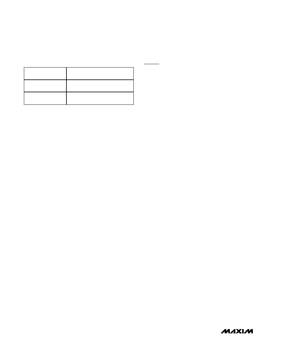
Command Address Auto-Incrementing
Address auto-incrementing allows the MAX5945 to be
configured with fewer transmissions by minimizing the
number of times the command address needs to be
sent. The command address stored in the MAX5945
generally increments after each data byte is written or
read (Table 4). The MAX5945 is designed to prevent
overwrites on unavailable register addresses and unin-
tentional wrap-around of addresses.
Register Map And Description
The interrupt register (Table 5) summarizes the event
register status and is used to send an interrupt signal
(INT goes low) to the controller. Writing a 1 to R1Ah[7]
clears all interrupt and events registers. A reset sets
R00h to 00h.
INT_EN (R17h[7]) is a global interrupt mask (Table 6).
The MASK_ bits activate the corresponding interrupt
bits in register R00h. Writing a 0 to INT_EN (R17h[7])
disables the INT output.
A reset sets R01h to AAA00A00b, where A is the state
of the AUTO input prior to the reset.
The power event register (Table 7) records changes in
the power status of the four ports. Any change in
PGOOD_ (R10h[7:4]) sets PG_CHG_ to 1. Any change
in the PWR_EN_ (R10h[3:0]) sets PWEN_CHG_ to 1.
PG_CHG_ and PWEN_CHG_ trigger on the edges of
PGOOD_ and PWR_EN_ and do not depend on the
actual level of the bits. The power event register has
two addresses. When read through the R02h address,
the content of the register is left unchanged. When read
through the CoR R03h address, the register content will
be cleared. A reset sets R02h/R03h = 00h.
DET_END_/CL_END_ is set high whenever detection/
classification is completed on the corresponding port.
A 1 in any of the CL_END_ bits forces R00h[4] to 1. A 1
in any of the DET_END_ bits forces R00h[3] to 1. As
with any other events register, the detect event register
(Table 8) has two addresses. When read through the
R04h address, the content of the register is left
unchanged. When read through the CoR R05h
address, the register content will be cleared. A reset
sets R04h/R05h = 00h.
LD_DISC_ is set high whenever the corresponding port
shuts down due to detection of load removal.
IMAX_FLT_ is set high when the port shuts down due to
an extended overcurrent event after a successful start-
up. A 1 in any of the LD_DISC_ bits forces R00h[2] to 1.
A 1 in any of the IMAX_FLT_ bits forces R00h[5] to 1.
As with any of the other events register, the fault event
register (Table 9) has two addresses. When read
through the R06h address, the content of the register is
left unchanged. When read through the CoR R07h
address, the register content will be cleared. A reset
sets R06h/R07h = 00h.
Quad Network Power Controller
for Power-Over-LAN
22
______________________________________________________________________________________
COMMAND BYTE
ADDRESS RANGE
AUTO-INCREMENT BEHAVIOR
0x00 to 0x26
Command address will auto-
increment after byte read or written
0x26
Command address remains at 0x26
after byte written or read
Table 4. Auto-Increment Rules
相關(guān)PDF資料 |
PDF描述 |
|---|---|
| PIC16F1933T-I/SO | MCU 8BIT 4K FLASH 28SOIC |
| VE-231-CV-S | CONVERTER MOD DC/DC 12V 150W |
| PIC16LF726T-I/SO | IC PIC MCU FLASH 8KX14 28-SOIC |
| PIC16F882-E/SS | IC PIC MCU FLASH 2KX14 28SSOP |
| DS2141AQ | IC CONTROLLER T1 5V 44-PLCC |
相關(guān)代理商/技術(shù)參數(shù) |
參數(shù)描述 |
|---|---|
| MAX5945CAX+ | 功能描述:熱插拔功率分布 IEEE 802.3af Quad Net Pwr Controller RoHS:否 制造商:Texas Instruments 產(chǎn)品:Controllers & Switches 電流限制: 電源電壓-最大:7 V 電源電壓-最小:- 0.3 V 工作溫度范圍: 功率耗散: 安裝風(fēng)格:SMD/SMT 封裝 / 箱體:MSOP-8 封裝:Tube |
| MAX5945CAX+T | 功能描述:熱插拔功率分布 IEEE 802.3af Quad Net Pwr Controller RoHS:否 制造商:Texas Instruments 產(chǎn)品:Controllers & Switches 電流限制: 電源電壓-最大:7 V 電源電壓-最小:- 0.3 V 工作溫度范圍: 功率耗散: 安裝風(fēng)格:SMD/SMT 封裝 / 箱體:MSOP-8 封裝:Tube |
| MAX5945CAX-T | 功能描述:熱插拔功率分布 RoHS:否 制造商:Texas Instruments 產(chǎn)品:Controllers & Switches 電流限制: 電源電壓-最大:7 V 電源電壓-最小:- 0.3 V 工作溫度范圍: 功率耗散: 安裝風(fēng)格:SMD/SMT 封裝 / 箱體:MSOP-8 封裝:Tube |
| MAX5945EAX | 功能描述:熱插拔功率分布 RoHS:否 制造商:Texas Instruments 產(chǎn)品:Controllers & Switches 電流限制: 電源電壓-最大:7 V 電源電壓-最小:- 0.3 V 工作溫度范圍: 功率耗散: 安裝風(fēng)格:SMD/SMT 封裝 / 箱體:MSOP-8 封裝:Tube |
| MAX5945EAX+ | 功能描述:熱插拔功率分布 IEEE 802.3af Quad Net Pwr Controller RoHS:否 制造商:Texas Instruments 產(chǎn)品:Controllers & Switches 電流限制: 電源電壓-最大:7 V 電源電壓-最小:- 0.3 V 工作溫度范圍: 功率耗散: 安裝風(fēng)格:SMD/SMT 封裝 / 箱體:MSOP-8 封裝:Tube |
發(fā)布緊急采購,3分鐘左右您將得到回復(fù)。