- 您現(xiàn)在的位置:買賣IC網(wǎng) > PDF目錄9799 > MAX3388ECUG+T (Maxim Integrated Products)IC TXRX RS232 250KBPS 24-TSSOP PDF資料下載
參數(shù)資料
| 型號: | MAX3388ECUG+T |
| 廠商: | Maxim Integrated Products |
| 文件頁數(shù): | 9/11頁 |
| 文件大?。?/td> | 0K |
| 描述: | IC TXRX RS232 250KBPS 24-TSSOP |
| 產(chǎn)品培訓(xùn)模塊: | Lead (SnPb) Finish for COTS Obsolescence Mitigation Program |
| 標(biāo)準(zhǔn)包裝: | 2,500 |
| 類型: | 收發(fā)器 |
| 驅(qū)動器/接收器數(shù): | 3/3 |
| 規(guī)程: | RS232 |
| 電源電壓: | 3 V ~ 5.5 V |
| 安裝類型: | 表面貼裝 |
| 封裝/外殼: | 24-TSSOP(0.173",4.40mm 寬) |
| 供應(yīng)商設(shè)備封裝: | 24-TSSOP |
| 包裝: | 帶卷 (TR) |

MAX3388E/MAX3389E
2.5V, ±15kV ESD-Protected RS-232
Transceivers for PDAs and Cell Phones
_______________________________________________________________________________________
7
shutdown is typically 30s, as shown in Figure 2.
Connect SHDN to VCC if the shutdown mode is not used.
In shutdown mode, the receiver outputs are high imped-
ance (Table 1).
VL Logic Supply Input
Unlike other RS-232 interface devices where the receiver
outputs swing between 0 and VCC, the MAX3388E/
MAX3389E feature a separate logic supply input (VL)
that sets VOH for the receiver outputs and sets thresh-
olds for the transmitter inputs. This feature allows a
great deal of flexibility in interfacing to many different
types of systems with different logic levels. Connect
this input to the host logic supply (1.8V
≤ VL ≤ VCC).
Also see the Typical PDA/Cell-Phone Application sec-
tion.
±15kV ESD Protection
As with all Maxim devices, ESD-protection structures are
incorporated on all pins to protect against ESDs encoun-
tered during handling and assembly. The MAX3388E/
MAX3389E’s driver outputs, receiver inputs, the hand-
shaking input LIN, and the switch terminal SWIN have
extra protection against static electricity. Maxim has
developed state-of-the-art structures to protect these pins
against an ESD of ±15kV without damage. The ESD
structures withstand high ESD in all states: normal opera-
tion, shutdown, and powered down. After an ESD event,
Maxim’s “E” version devices keep working without
latchup, whereas competing RS-232 products can latch
and must be powered down to remove latchup. ESD pro-
tection can be tested in various ways. The transmitter out-
puts and receiver inputs of this product family are
characterized for protection to the following limits:
1) ±15kV using the Human Body Model
2) ±8kV using the Contact Discharge method specified
in IEC 1000-4-2
3) ±15kV using IEC 1000-4-2’s Air-Gap Discharge
method
ESD Test Conditions
ESD performance depends on a variety of conditions.
Contact Maxim for a reliability report that documents
test setup, methodology, and results.
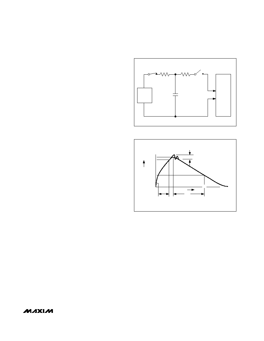
Human Body Model
Figure 3a shows the Human Body Model, and Figure 3b
shows the current waveform it generates when dis-
charged into a low impedance. This model consists of
a 100pF capacitor charged to the ESD voltage of interest,
which is then discharged into the test device through a
1.5k
resistor.
IEC 1000-4-2
The IEC 1000-4-2 standard covers ESD testing and
performance of finished equipment; it does not specifi-
cally refer to ICs. The MAX3388E/MAX3389E helps you
design equipment that meets Level 4 (the highest level)
of IEC 1000-4-2, without the need for additional ESD-
protection components.
The major difference between tests done using the
Human Body Model and IEC 1000-4-2 is higher peak
current in IEC 1000-4-2, because series resistance is
lower in the IEC 1000-4-2 model. Hence, the ESD with-
stand voltage measured to IEC 1000-4-2 is generally
lower than that measured using the Human Body
Model. Figure 4a shows the IEC 1000-4-2 model, and
Figure 4b shows the current waveform for the ±8kV IEC
1000-4-2 Level 4 ESD Contact Discharge test.
CHARGE-CURRENT
LIMIT RESISTOR
DISCHARGE
RESISTANCE
STORAGE
CAPACITOR
Cs
100pF
RC
1M
RD
1500
HIGH-
VOLTAGE
DC
SOURCE
DEVICE
UNDER
TEST
Figure 3a. Human Body ESD Test Model
IP 100%
90%
36.8%
tRL
TIME
tDL
CURRENT WAVEFORM
PEAK-TO-PEAK RINGING
(NOT DRAWN TO SCALE)
Ir
10%
0
AMPERES
Figure 3b. Human Body Current Waveform
相關(guān)PDF資料 |
PDF描述 |
|---|---|
| AD9215BRU-80 | IC ADC 10BIT 80MSPS 3V 28-TSSOP |
| V150C15M150BG3 | CONVERTER MOD DC/DC 15V 150W |
| AD9051BRS | IC ADC 10BIT 60MSPS 28-SSOP |
| V150C15M150BG | CONVERTER MOD DC/DC 15V 150W |
| AD7713AR | IC ADC SIGNAL COND LC2MOS 24SOIC |
相關(guān)代理商/技術(shù)參數(shù) |
參數(shù)描述 |
|---|---|
| MAX3388EEUG | 功能描述:RS-232接口集成電路 RoHS:否 制造商:Exar 數(shù)據(jù)速率:52 Mbps 工作電源電壓:5 V 電源電流:300 mA 工作溫度范圍:- 40 C to + 85 C 安裝風(fēng)格:SMD/SMT 封裝 / 箱體:LQFP-100 封裝: |
| MAX3388EEUG+ | 功能描述:RS-232接口集成電路 2.5V Transceiver for PDAs & Cells RoHS:否 制造商:Exar 數(shù)據(jù)速率:52 Mbps 工作電源電壓:5 V 電源電流:300 mA 工作溫度范圍:- 40 C to + 85 C 安裝風(fēng)格:SMD/SMT 封裝 / 箱體:LQFP-100 封裝: |
| MAX3388EEUG+T | 功能描述:RS-232接口集成電路 2.5V Transceiver for PDAs & Cells RoHS:否 制造商:Exar 數(shù)據(jù)速率:52 Mbps 工作電源電壓:5 V 電源電流:300 mA 工作溫度范圍:- 40 C to + 85 C 安裝風(fēng)格:SMD/SMT 封裝 / 箱體:LQFP-100 封裝: |
| MAX3388EEUG-T | 功能描述:RS-232接口集成電路 RoHS:否 制造商:Exar 數(shù)據(jù)速率:52 Mbps 工作電源電壓:5 V 電源電流:300 mA 工作溫度范圍:- 40 C to + 85 C 安裝風(fēng)格:SMD/SMT 封裝 / 箱體:LQFP-100 封裝: |
| MAX3389ECUG | 功能描述:RS-232接口集成電路 RoHS:否 制造商:Exar 數(shù)據(jù)速率:52 Mbps 工作電源電壓:5 V 電源電流:300 mA 工作溫度范圍:- 40 C to + 85 C 安裝風(fēng)格:SMD/SMT 封裝 / 箱體:LQFP-100 封裝: |
發(fā)布緊急采購,3分鐘左右您將得到回復(fù)。