- 您現(xiàn)在的位置:買賣IC網(wǎng) > PDF目錄383359 > MAX3218* (Maxim Integrated Products, Inc.) 1µ.A.1.8V to 4.25V RS-232 Transceiver with AutoShutdown™. PDF資料下載
參數(shù)資料
| 型號: | MAX3218* |
| 廠商: | Maxim Integrated Products, Inc. |
| 英文描述: | 1µ.A.1.8V to 4.25V RS-232 Transceiver with AutoShutdown™. |
| 文件頁數(shù): | 8/12頁 |
| 文件大小: | 123K |
M
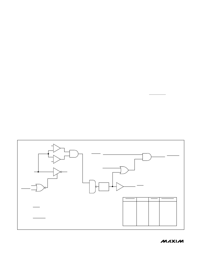
MAX3218 shuts down after sensing invalid RS-232 levels
for greater than 30μs, ensuring that the AutoShutdown
mode is not enabled for slow-moving signals (>1V/μs).
Another system with AutoShutdown may need a period
of time to wake up. Figure 5 shows a circuit that forces
the transmitters on for 100ms after start-up, allowing
enough time for the other system to realize that the
MAX3218 system is awake. If the other system outputs
valid RS-232 signals within that time, the RS-232 ports on
both systems remain enabled.
__________Applic ations Information
Operation from Regulated/Unregulated
Dual S ystem Power S upplies
The MAX3218 is intended for use with three different
power-supply sources: it can be powered directly from
a battery, from a 3.0V or 3.3V power supply, or simulta-
neously from both. Figure 1 shows the single-supply
configuration. Figure 6 shows the circuit for operation
from both a 3V supply and a raw battery supply—an
ideal configuration where a regulated 3V supply is
being derived from two cells. In this application, the
MAX3218’s logic levels remain appropriate for interface
with 3V logic, yet most of the power for the MAX3218 is
drawn directly from the battery, without suffering the
efficiency losses of the DC-DC converter. This pro-
longs battery life.
Bypass the input supplies with 0.1μF at V
CC
(C4) and at
least 1μF at the inductor (C5). Increase C5 to 4.7μF if
the power supply has no other bypass capacitor con-
nected to it.
Low-Power Operation
The following suggestions will help you get maximum
life out of your batteries.
Transmit at the highest practical data rate. Although
this raises the supply current while transmission is in
progress, the transmission will be over sooner. If the
MAX3218 is shut down (using FORCEOFF) as soon as
each transmission ends, this practice will save energy.
Operate your whole system from the raw battery volt-
age rather than suffer the losses of a regulator or DC-
DC converter. If this is not possible, but your system is
powered from two cells and employs a 3V DC-DC con-
verter to generate the main logic supply, use the circuit
of Figure 6. This circuit draws most of the MAX3218’s
power straight from the battery, but still provides logic-
level compatibility with the 3V logic.
1μA S upply Current, 1.8V to 4.25V-Powered
RS -232 Transc eiver with AutoS hutdown
8
_______________________________________________________________________________________
INVALID IS AN INTERNALLY GENERATED SIGNAL
THAT IS USED BY THE AUTOSHUTDOWN LOGIC
AND APPEARS AS AN OUTPUT OF THE DEVICE.
POWER DOWN IS ONLY AN INTERNAL SIGNAL.
IT CONTROLS THE OPERATIONAL STATUS OF
THE TRANSMITTERS AND THE POWER SUPPLIES.
FORCEOFF
0
0
0
0
1
1
1
1
FORCEON
0
0
1
1
0
0
1
1
INVALID
0
1
0
1
0
1
0
1
POWER DOWN
0
0
0
0
0
1
1
1
POWER DOWN
FORCEOFF
FORCEON
INVALID
+
-
+
-
Rx
R_IN
FORCEON
FORCEOFF
R_OUT
30μs
DELAY
+0.3V to +2.8V
-0.3V to -2.8V
Figure 3. AutoShutdown Logic
相關PDF資料 |
PDF描述 |
|---|---|
| MAX3224ECPP | 5V High-Speed RS-232 Transceivers with 0.1uF Capacitors |
| MAX3224E | 5V High-Speed RS-232 Transceivers with 0.1uF Capacitors |
| MAX3224ECAP | 5V High-Speed RS-232 Transceivers with 0.1uF Capacitors |
| MAX3224EEPP | Digital Media Processor 376-BGA |
| MAX3225ECAP | 5V High-Speed RS-232 Transceivers with 0.1uF Capacitors |
相關代理商/技術參數(shù) |
參數(shù)描述 |
|---|---|
| MAX3218C/D | 功能描述:RS-232接口集成電路 RoHS:否 制造商:Exar 數(shù)據(jù)速率:52 Mbps 工作電源電壓:5 V 電源電流:300 mA 工作溫度范圍:- 40 C to + 85 C 安裝風格:SMD/SMT 封裝 / 箱體:LQFP-100 封裝: |
| MAX3218CAP | 功能描述:RS-232接口集成電路 Integrated Circuits (ICs) RoHS:否 制造商:Exar 數(shù)據(jù)速率:52 Mbps 工作電源電壓:5 V 電源電流:300 mA 工作溫度范圍:- 40 C to + 85 C 安裝風格:SMD/SMT 封裝 / 箱體:LQFP-100 封裝: |
| MAX3218CAP+ | 功能描述:RS-232接口集成電路 1uA 1.8-4.25V Tcvr w/AutoShutdown RoHS:否 制造商:Exar 數(shù)據(jù)速率:52 Mbps 工作電源電壓:5 V 電源電流:300 mA 工作溫度范圍:- 40 C to + 85 C 安裝風格:SMD/SMT 封裝 / 箱體:LQFP-100 封裝: |
| MAX3218CAP+ | 制造商:Maxim Integrated Products 功能描述:SEMICONDUCTOR ((NW)) |
| MAX3218CAP+T | 功能描述:RS-232接口集成電路 1uA 1.8-4.25V Tcvr w/AutoShutdown RoHS:否 制造商:Exar 數(shù)據(jù)速率:52 Mbps 工作電源電壓:5 V 電源電流:300 mA 工作溫度范圍:- 40 C to + 85 C 安裝風格:SMD/SMT 封裝 / 箱體:LQFP-100 封裝: |
發(fā)布緊急采購,3分鐘左右您將得到回復。