- 您現(xiàn)在的位置:買賣IC網(wǎng) > PDF目錄383346 > MAX2510EEI (MAXIM INTEGRATED PRODUCTS INC) Low-Voltage IF Transceiver with Limiter/RSSI and Quadrature Modulator PDF資料下載
參數(shù)資料
| 型號: | MAX2510EEI |
| 廠商: | MAXIM INTEGRATED PRODUCTS INC |
| 元件分類: | 通信及網(wǎng)絡(luò) |
| 英文描述: | Low-Voltage IF Transceiver with Limiter/RSSI and Quadrature Modulator |
| 中文描述: | SPECIALTY TELECOM CIRCUIT, PDSO28 |
| 封裝: | QSOP-28 |
| 文件頁數(shù): | 10/12頁 |
| 文件大?。?/td> | 126K |
| 代理商: | MAX2510EEI |
M
Received Signal-Strength Indicator
The RSSI output provides a linear indication of the
received power level on the LIMIN input. The RSSI
monotonic dynamic range exceeds 90dB while provid-
ing better than 80dB linear range. The RSSI output
pulses current into a 330pF (typical) external filter
capacitor. The output is internally terminated to ground
with 11k
, and this R-C time constant sets the decay
time. The rise time is limited by the RSSI pin’s output
drive current. The rise time is typically less than 100ns
with no capacitor connected. Larger capacitor values
slow the rise time.
T ransmitter
The I,
I
and Q,
Q
baseband signals are input to a pair
of double-balanced mixers, which are driven from a
quadrature LO source. The quadrature LO is generated
on-chip from the oscillator input present at the LO and
LO
pins. The two mixers’ outputs are summed. With
quadrature baseband inputs at the I,
I
and Q,
Q
pins,
the unwanted sideband is largely canceled. The result-
ing signal from the mixers is fed through a variable-gain
amplifier (VGA) with more than 40dB of gain-adjust
range.
The VGA output is connected to a driver amplifier with
an output 1dB compression point of +2dBm. The out-
put power can be adjusted from approximately +2dBm
to -40dBm by controlling the GC pin. The resulting sig-
nal appears as a differential output on the TXOUT and
TXOUT
pins.
TXOUT and
TXOUT
are open-collector outputs and
need external pull-up inductors to V
CC
for proper oper-
ation, as well as a DC block so the load does not affect
DC biasing. A shunt resistor across TXOUT and
TXOUT
(100
typical) can be used to back terminate an exter-
nal filter, as shown in the Typical Operating Circuit
Alternatively, a single-ended load can be connected to
TXOUT, as long as
TXOUT
is tied directly to V
CC
. Refer
to the Applications Informationsection for details.
Loc al-Osc illator Inputs
The MAX2510 requires an external LO source for the
mixers. LO and
LO
are high-impedance inputs (>1k
).
The external LO signal is buffered internally and fed to
both the receive mixer and the LO phase shifter used
for the transmit mixers.
In a typical application, externally terminate the LO
source with a 50
resistor and then AC couple into LO.
Typically, the LO power range should be -13dBm to
0dBm (into 50
). Connect a bypass capacitor from
LO
to ground. Alternatively, a differential LO source (exter-
nally terminated) can drive LO and
LO
through series
coupling capacitors.
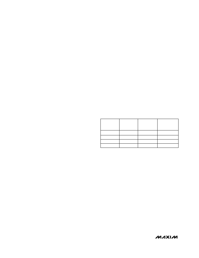
Power Management
To provide advanced system power management, the
MAX2510 features four operating modes that are
selected via the RXEN and TXEN pins, according to
Table 1 (supply currents assume GC = 0.5V).
In shutdown mode, all part functions are off. Standby
mode allows fastest enabling of either transmit or receive
mode by keeping the VREF generator active. This avoids
delays in stabilizing the limiter input circuitry and the off-
set correction loop. Transmit mode enables the LO
buffer, LO phase shifter, upconverter mixer, transmit
VGA, and transmit output driver amplifier. Receive mode
enables the LO buffer, downconverter mixer, limiting
amplifier, and RSSI functions.
Table 1. Power-Supply Mode Selection
__________Applic ations Information
RX Input Matc hing
The RXIN,
RXIN
port typically needs an impedance
matching network for proper connection to external cir-
cuitry, such as a filter. See the Typical Operating Circuit
for an example circuit topology. Note that the receiver
input can be driven either single-ended or differentially.
The component values used in the matching network
depend on the desired operating frequency as well as
on filter impedance. The following table indicates the
RXIN,
RXIN
single-ended input impedance (that is,
the impedance looking into either RXIN or
RXIN
). The
information in Table 2 is also plotted in the Typical
Operating Characteristics.
Low-Voltage IF Transc eiver with
Limiter/RS S I and Quadrature Modulator
10
______________________________________________________________________________________
High
Low
High
TXEN
STATE
Low
0.5m
14m
17m
TYPICAL
SUPPLY
CURRENT (A)
0.2μ
Standby
Receive
Transmit
MODE
Shutdown
High
High
Low
RXEN
STATE
Low
相關(guān)PDF資料 |
PDF描述 |
|---|---|
| MAX2510 | Low-Voltage IF Transceiver with Limiter/RSSI and Quadrature Modulator |
| MAX252AEHG | Circular Connector; No. of Contacts:19; Series:MS27466; Body Material:Aluminum; Connecting Termination:Crimp; Connector Shell Size:25; Circular Contact Gender:Pin; Circular Shell Style:Wall Mount Receptacle; Insert Arrangement:25-19 RoHS Compliant: No |
| MAX252 | 5V High-Speed RS-232 Transceivers with 0.1uF Capacitors |
| MAX252BCHL | 5V High-Speed RS-232 Transceivers with 0.1uF Capacitors |
| MAX2511 | BCD-To-Decimal Decoders/Drivers 16-PDIP 0 to 70 |
相關(guān)代理商/技術(shù)參數(shù) |
參數(shù)描述 |
|---|---|
| MAX2510EEI+ | 功能描述:射頻收發(fā)器 IF Txr w/Limitr RSSI Quadrature Mod RoHS:否 制造商:Atmel 頻率范圍:2322 MHz to 2527 MHz 最大數(shù)據(jù)速率:2000 Kbps 調(diào)制格式:OQPSK 輸出功率:4 dBm 類型: 工作電源電壓:1.8 V to 3.6 V 最大工作溫度:+ 85 C 接口類型:SPI 封裝 / 箱體:QFN-32 封裝:Tray |
| MAX2510EEI+T | 功能描述:射頻收發(fā)器 IF Txr w/Limitr RSSI Quadrature Mod RoHS:否 制造商:Atmel 頻率范圍:2322 MHz to 2527 MHz 最大數(shù)據(jù)速率:2000 Kbps 調(diào)制格式:OQPSK 輸出功率:4 dBm 類型: 工作電源電壓:1.8 V to 3.6 V 最大工作溫度:+ 85 C 接口類型:SPI 封裝 / 箱體:QFN-32 封裝:Tray |
| MAX2510EEI-T | 功能描述:射頻收發(fā)器 RoHS:否 制造商:Atmel 頻率范圍:2322 MHz to 2527 MHz 最大數(shù)據(jù)速率:2000 Kbps 調(diào)制格式:OQPSK 輸出功率:4 dBm 類型: 工作電源電壓:1.8 V to 3.6 V 最大工作溫度:+ 85 C 接口類型:SPI 封裝 / 箱體:QFN-32 封裝:Tray |
| MAX2510EVKIT-SO | 功能描述:射頻開發(fā)工具 MAX2510 Eval Kit RoHS:否 制造商:Taiyo Yuden 產(chǎn)品:Wireless Modules 類型:Wireless Audio 工具用于評估:WYSAAVDX7 頻率: 工作電源電壓:3.4 V to 5.5 V |
| MAX2511EEI | 功能描述:射頻收發(fā)器 IF Txr w/Limitr RSSI RoHS:否 制造商:Atmel 頻率范圍:2322 MHz to 2527 MHz 最大數(shù)據(jù)速率:2000 Kbps 調(diào)制格式:OQPSK 輸出功率:4 dBm 類型: 工作電源電壓:1.8 V to 3.6 V 最大工作溫度:+ 85 C 接口類型:SPI 封裝 / 箱體:QFN-32 封裝:Tray |
發(fā)布緊急采購,3分鐘左右您將得到回復(fù)。