- 您現(xiàn)在的位置:買賣IC網(wǎng) > PDF目錄384656 > MAX2402EAP (MAXIM INTEGRATED PRODUCTS INC) Analog IC PDF資料下載
參數(shù)資料
| 型號(hào): | MAX2402EAP |
| 廠商: | MAXIM INTEGRATED PRODUCTS INC |
| 元件分類: | 通信及網(wǎng)絡(luò) |
| 英文描述: | Analog IC |
| 中文描述: | SPECIALTY TELECOM CIRCUIT, PDSO20 |
| 封裝: | SSOP-20 |
| 文件頁(yè)數(shù): | 5/6頁(yè) |
| 文件大?。?/td> | 65K |
| 代理商: | MAX2402EAP |
BADJ can be left open or adjusted with a single pull-
up or pull-down resistor to V
CC
or GND, respectively.
The value of this resistor determines the amount of
adjustment applied. A single resistor results in no cur-
rent flow at BADJ during power-down (whereas a
resistor divider always has current flowing through the
resistors). Table 1 shows the approximate bias adjust
voltage at the pin for different resistor values. At lower
LO frequencies, where the transmitter gain and output
power is the highest, setting BADJ to a low voltage
(maximum bias current) causes excessive current in
the output and can cause unstable behavior in the IC.
At lower LO frequencies (around 800MHz), more than
22dBm of power is easily obtained with BADJ set for
3V or more. If higher bias current and less distortion is
desired in the 800MHz range, using a lower inductor
value on LGND (pin 11) (see the Typical Application
Circuit might make the desired bias level stable. At
higher frequencies (near 1000MHz), a lower bias level
voltage results in more power (see the Output Power vs.
Bias Control Voltage vs. Frequency graph in the Typical
Operating Characteristics.
Power Amplifier Output
The power amplifier has an open-collector output that
can drive into a load of 30
to 50
; however, maximum
power transfer is obtained at about 35
. 27nH to
ground is recommended on LGND (pin 11), as shown
in the Typical Application Circuit This inductor is used
as a current source on the base of the output stage to
pull stored charge out of the base.
S HDN Input
The SHDN input completely shuts down the current
from the supply and all signal pins when switched
below 0.5V. During normal operation, SHDN should
remain above V
CC
- 0.5V.
The shutdown control shuts down the total current to
below 150nA (typ). Power-up occurs within 10μs.
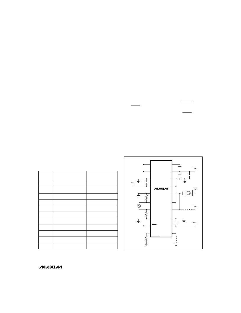
__________Applic ations Information
The MAX2402 transmitter operates within the 800MHz
to 1000MHz frequency range. Figure 1 shows a typical
application circuit. Additional applications information
can be obtained from the MAX2402 evaluation kit
manual.
M
800MHz to 1000MHz Transmitter
_______________________________________________________________________________________
5
Resistor
Value (
)
BADJ with Resistor
Connected to GND (V)*
BADJ with Resistor
Connected to V
CC
(V)
10k
0.36
4.54
20k
0.63
4.27
30k
0.84
4.05
40k
1.00
3.89
50k
1.13
3.75
100k
1.54
3.34
200k
1.89
3.00
300k
2.05
2.85
400k
2.13
2.75
500k
2.20
2.68
1M
2.31
2.57
Figure 1. Typical Application Circuit
MAX2402
BADJ
300k
50
39pF
50
27nH
SHDN
GND
LO-
LO+
GND
V
CC
V
CC
GND
MOD
VGC
LGND
V
CC
GND
OUT
GND
VCO
MODULATION
SHUTDOWN
CONTROL
VARIABLE
GAIN CONTROL
OUT
GND
GND
V
CC
GND
39pF
47nH
V
CC
V
CC
39pF
0.01
μ
F
V
CC
1
2
3
4
5
6
7
8
9
10
20
19
18
17
16
15
14
13
12
11
Table 1. Bias-Adjust Voltage for Various
Resistor Values
* Typical variation of BADJ over temperature and process is
less than 5%.
相關(guān)PDF資料 |
PDF描述 |
|---|---|
| MAX2430ISE | Low-Voltage, Silicon RF Power Amplifier/Predriver |
| MAX2430IEE | Low-Voltage, Silicon RF Power Amplifier/Predriver |
| MAX2430 | Low-Voltage, Silicon RF Power Amplifier/Predriver |
| MAX2450 | 3V, Ultra-Low-Power Quadrature Modulator/Demodulator |
| MAX2450CEP | 3V, Ultra-Low-Power Quadrature Modulator/Demodulator |
相關(guān)代理商/技術(shù)參數(shù) |
參數(shù)描述 |
|---|---|
| MAX2403ETI | 功能描述:調(diào)節(jié)器/解調(diào)器 RoHS:否 制造商:Texas Instruments 封裝 / 箱體:PVQFN-N24 封裝:Reel |
| MAX2403ETI+ | 功能描述:調(diào)節(jié)器/解調(diào)器 RoHS:否 制造商:Texas Instruments 封裝 / 箱體:PVQFN-N24 封裝:Reel |
| MAX2403ETI+T | 功能描述:調(diào)節(jié)器/解調(diào)器 RoHS:否 制造商:Texas Instruments 封裝 / 箱體:PVQFN-N24 封裝:Reel |
| MAX2403ETI-T | 功能描述:調(diào)節(jié)器/解調(diào)器 RoHS:否 制造商:Texas Instruments 封裝 / 箱體:PVQFN-N24 封裝:Reel |
| MAX2403EVKIT | 功能描述:射頻開(kāi)發(fā)工具 RoHS:否 制造商:Taiyo Yuden 產(chǎn)品:Wireless Modules 類型:Wireless Audio 工具用于評(píng)估:WYSAAVDX7 頻率: 工作電源電壓:3.4 V to 5.5 V |
發(fā)布緊急采購(gòu),3分鐘左右您將得到回復(fù)。