- 您現(xiàn)在的位置:買(mǎi)賣(mài)IC網(wǎng) > PDF目錄385524 > MAX2385EBP-T (MAXIM INTEGRATED PRODUCTS INC) CDMA + GPS LNA/Mixers PDF資料下載
參數(shù)資料
| 型號(hào): | MAX2385EBP-T |
| 廠商: | MAXIM INTEGRATED PRODUCTS INC |
| 元件分類(lèi): | 無(wú)繩電話/電話 |
| 英文描述: | CDMA + GPS LNA/Mixers |
| 中文描述: | TELECOM, CELLULAR, RF AND BASEBAND CIRCUIT, PBGA20 |
| 封裝: | 2.10 X 2.70 MM, UCSP-20 |
| 文件頁(yè)數(shù): | 9/18頁(yè) |
| 文件大小: | 216K |
| 代理商: | MAX2385EBP-T |
第1頁(yè)第2頁(yè)第3頁(yè)第4頁(yè)第5頁(yè)第6頁(yè)第7頁(yè)第8頁(yè)當(dāng)前第9頁(yè)第10頁(yè)第11頁(yè)第12頁(yè)第13頁(yè)第14頁(yè)第15頁(yè)第16頁(yè)第17頁(yè)第18頁(yè)
Detailed Description
The MAX2385/MAX2386 are ideal for CDMA + GPS
applications. These devices contain two LNA/mixer
pairs: one pair for CDMA operation and one pair for
GPS operation. The MAX2385/MAX2386 feature seven
modes of operation, including shutdown. Table 1
depicts each mode along with the corresponding LNA
and mixer configuration.
These devices are ideal for Japanese cdma2000 1x
applications. The RF frequency range is from 832MHz
to 870MHz, and the IF frequency range is from 70MHz
to 200MHz. In GPS mode, the RF frequency is
1575.42MHz. These devices can also be used for the
Korean/Chinese/U.S. 869MHz to 894MHz band.
CDMA LNA
The MAX2385/MAX2386 have four modes of CDMA
LNA operation: high gain, high linearity (HGHL); high
gain, low linearity (HGLL); midgain (MG); and low gain
(LG). The logic inputs MODE, G1, and G2 allow selec-
tion between these modes (Table 1). Use HGHL mode
when extra-high linearity is required for cross-modula-
tion suppression. When cross-modulation is not a con-
cern or the transmitter is off, use HGLL mode. In
MG mode, the device is designed to meet CDMA
linearity with interferers at -32dBm/tone. When
M
CDMA + GPS LNA/Mixers
_______________________________________________________________________________________
9
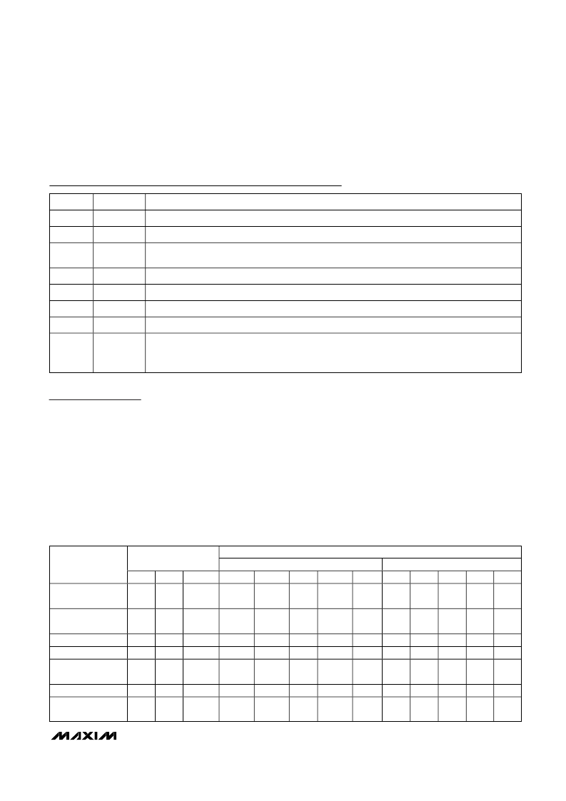
PIN
NAME
FUNCTION
C3
G2
Logic Input (Table 1)
D3
V
CC
+2.7 to +3.6V Supply Pin. Bypass with 100pF capacitor as close to the pin as possible.
B4, C4
CIF-, CIF+
CDMA Differential Output Port. Requires pullup inductors and blocking capacitors, which are used as
part of the matching network.
D4
GND
Ground
A5
CMIXIN
CDMA Mixer Input Port. Requires a series blocking capacitor.
B5
GND
Ground
C5
LO_OUT
LO Buffer Output Port. Internally matched to 100
. Requires a series blocking capacitor.
D5
LO_IN
LO Input Port. Also LO buffer enable (BUFFEN). Apply logic signal through 10k
resistor. Set LO_IN
high to enable the LO_OUT port. Set low to disable the LO_OUT port. AC-couple the LO input and DC-
couple the buffer enable signal (see
Typical Operating Circuit
).
Pin Description (continued)
Table 1. Mode Selection Truth Table
FUNCTION
CONTROL PINS
LNA
MG
MIXER
LG
MODES
G1
G2
MODE
HGHL
HGLL
LGHL
GPS
HG
MG
UL
GPS
High Gain, High
Linearity (HGHL)
0
0
1
G
—
—
—
—
G
—
—
—
—
High Gain, Low
Linearity (HGLL)
1
1
0
—
G
—
—
—
G
—
—
—
—
Midgain (MG)
Low Gain (LG)
1
1
0
1
1
1
—
—
—
—
G
—
—
—
—
—
G
—
—
—
—
—
—
G
—
G
Ultra-Low Gain
(ULG)
1
0
0
—
—
—
G
—
—
—
—
G
—
GPS
0
1
1
—
—
—
—
G
—
—
—
—
G
Shutdown
(SHDN)
0
X
0
—
—
—
—
—
—
—
—
—
—
相關(guān)PDF資料 |
PDF描述 |
|---|---|
| MAX2386EBP-T | CDMA + GPS LNA/Mixers |
| MAX2394 | MAX2394/MAX2395 Evaluation Kits |
| MAX2395 | MAX2394/MAX2395 Evaluation Kits |
| MAX2396 | Evaluation Kit |
| MAX2402EVKIT-SO | Evaluation Kit |
相關(guān)代理商/技術(shù)參數(shù) |
參數(shù)描述 |
|---|---|
| MAX2385EVKIT | 功能描述:射頻開(kāi)發(fā)工具 RoHS:否 制造商:Taiyo Yuden 產(chǎn)品:Wireless Modules 類(lèi)型:Wireless Audio 工具用于評(píng)估:WYSAAVDX7 頻率: 工作電源電壓:3.4 V to 5.5 V |
| MAX2386EBP | 制造商:Maxim Integrated Products 功能描述:CDMA + GPS LNA/MIXERS - Rail/Tube |
| MAX2386EBP-T | 功能描述:射頻混合器 RoHS:否 制造商:NXP Semiconductors 頻率范圍: 轉(zhuǎn)換損失——最大: 工作電源電壓:6 V 最大工作溫度:+ 85 C 最小工作溫度:- 40 C 安裝風(fēng)格:Through Hole 封裝 / 箱體:PDIP-8 封裝:Tube |
| MAX2386EVKIT | 功能描述:射頻開(kāi)發(fā)工具 RoHS:否 制造商:Taiyo Yuden 產(chǎn)品:Wireless Modules 類(lèi)型:Wireless Audio 工具用于評(píng)估:WYSAAVDX7 頻率: 工作電源電壓:3.4 V to 5.5 V |
| MAX2387EGC | 功能描述:射頻混合器 RoHS:否 制造商:NXP Semiconductors 頻率范圍: 轉(zhuǎn)換損失——最大: 工作電源電壓:6 V 最大工作溫度:+ 85 C 最小工作溫度:- 40 C 安裝風(fēng)格:Through Hole 封裝 / 箱體:PDIP-8 封裝:Tube |
發(fā)布緊急采購(gòu),3分鐘左右您將得到回復(fù)。