- 您現在的位置:買賣IC網 > PDF目錄224182 > M83733/7RA051 (ITT CANNON) 51 CONTACT(S), FEMALE, MULTIWAY RACK AND PANEL CONN, CRIMP, PLUG PDF資料下載
參數資料
| 型號: | M83733/7RA051 |
| 廠商: | ITT CANNON |
| 元件分類: | 多腳機架和面板連接器 |
| 英文描述: | 51 CONTACT(S), FEMALE, MULTIWAY RACK AND PANEL CONN, CRIMP, PLUG |
| 文件頁數: | 9/17頁 |
| 文件大?。?/td> | 444K |
| 代理商: | M83733/7RA051 |
MIL-C-83733
DPK
Coaxial Contact/Assembly
93
www.ittcannon.com
Dimensions shown in inch (mm)
Specifications and dimensions subject to change
249-5500-010 Socket*
249-5500-011 PIN*
249-5500-012 Socket*
249-5500-013 PIN*
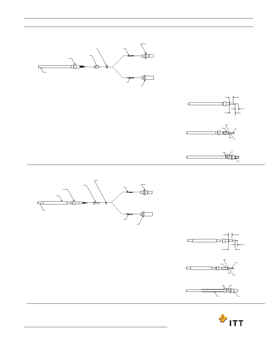
INSULATOR, BEAD
CONTACT, PIN
BODY ASSEMBLY
1. These assembly instructions apply to 249-5500-010,
and 249-5500-011.
2. The following assembly tools are required:
a) CCT-C9 hex crimp tool
b) MS3198-Q W/L-3198-C1 contact crimp tool and
locator
c) 149 C(300 F) hot air gun (recommended): Regal
heat Gun No. 9A)
d) Blades, scissors, and picks
BODY ASSEMBLY
13/64 +_ 1/64
(5.16 +_ 0.40)
3/16 +_ 1/64
(4.76 +_ 0.40)
13/64 +_ 1/64
(5.16 +_ 0.40)
1/8 +_ 1/64
(3.18 +_ 0.40)
3/8 +_ 1/64
(9.52 +_ 0.40)
5/16 +_ 1/64
(7.94 +_ 0.40)
BODY INSERT
INSULATOR, BEAD
HEX CRIMP
RING, OUTER
BODY ASSEMBLY
CENTER CONDUCTOR
MUST BE VISIBLE
IN INSEPECTION HOLE
8 INDENT CRIMP
CONTACT, PIN
OR SOCKET
BODY INSERT
INSULATOR, BEAD
HEX CRIMP
SLEEVE,
HEAT SHRINK
RING, OUTER
BODY ASSEMBLY
CENTER CONDUCTOR
MUST BE VISIBLE
IN INSEPECTION HOLE
8 INDENT CRIMP
CONTACT, PIN
OR SOCKET
CONTACT, SOCKET
BODY INSERT
RING, OUTER
STEP 1.
STEP 2.
STEP 3.
STEP 4.
STEP 1.
STEP 5.
STEP 6.
STEP 7.
STEP 2.
STEP 3.
STEP 4.
STEP 5.
NOTES:
1. These assembly instructions apply to 249-5500-010,
and 249-5500-011.
2. The following assembly tools are required:
a) CCT-C9 hex crimp tool
b) M22520/2-01 contact crimp tool and locator
c) 149 C(300 F) hot air gun (recommended): Regal
heat Gun No. 9A)
d) Blades, scissors, and picks
NOTES:
STEP 6.
INSULATOR, BEAD
CONTACT, PIN
BODY ASSEMBLY
BODY INSERT
RING, OUTER
SLEEVE
HEAT SHRINK
COAXIAL CABLE
RG-188/U
CONTACT, SOCKET
COAXIAL CABLE
RG-180/U OR RG-195/U
Slide outer ring over cable as shown (Figure 1).
Slide body assembly over componenets and under shield until firmly
bottomed in place. Locate outer ring over shield and against body as
shown (Figure 3).
With cable and body assembly securely held together, hex crimp the
outer ring with tool CCT-C9 (Figure 3). Important: For optimum hex
crimp, firmly bottom the outer ring against the shoulder of the hex die
before compressing the handles.
The final step is to shrink the heat sleeve in place with a hot air source
of 149 C to 327 C (300 F to 621 F) (Figure 3).
Strip cable as shown (Figure 1).
Install body insert, insulatro bed, and contact on cable as shown
(Figure 2.)
With body insert, insulator bead, and contact firmly in place, crimp the
contact with tool M22520/2-01 (setting number 3) and loacator
M22520/2-30 (Figure 2). Caution: The assembled componenets must
be tightly in place after crimping.
With body insert, insulator bead, and contact firmly in place, crimp the
contact with tool M22520/2-01, using setting number 3 and loacator
M22520/2-30 (Figure 2). Caution: The assembled componenets must
be tightly in place after crimping.
Slide heat-shrink sleeve and outer ring over cable as shown.
Strip cable as shown (Figure 1). Caution: Do not nick shield wires.
Install body insert, insulator bead, and contact on cable as shown.
*These contacts are used in the F59C7 layout.
*These contacts are used in the G59C7 layout.
相關PDF資料 |
PDF描述 |
|---|---|
| M83733/7RA131 | 131 CONTACT(S), FEMALE, MULTIWAY RACK AND PANEL CONN, CRIMP, PLUG |
| M83733/8RA051 | 51 CONTACT(S), MALE, MULTIWAY RACK AND PANEL CONN, CRIMP, RECEPTACLE |
| M83734/1-033 | DIP6, IC SOCKET |
| M83734/10-031 | DIP40, IC SOCKET |
| M83734/15-032 | DIP64, IC SOCKET |
相關代理商/技術參數 |
參數描述 |
|---|---|
| M83734/10-032 | 制造商:Mill-Max Mfg Corp 功能描述: |
| M83734/13-013 | 制造商:MIL SPECS 功能描述: 制造商:PRECIC 功能描述: 制造商:PRECICONTACT INC 功能描述: 制造商:PRECICONTACT INC. 功能描述: |
| M83734/13-014 | 制造商:PRECIC 功能描述: 制造商:PRECICONTACT INC 功能描述: |
| M83734/13-031 | 制造商: 功能描述: 制造商:undefined 功能描述: |
| M83734/14-032 | 制造商:MIL SPECS 功能描述: |
發(fā)布緊急采購,3分鐘左右您將得到回復。