- 您現(xiàn)在的位置:買賣IC網(wǎng) > PDF目錄370991 > M66004SP (Mitsubishi Electric Corporation) null16-DIGIT 5x7-SEGMENT VFD CONTROLLER PDF資料下載
參數(shù)資料
| 型號: | M66004SP |
| 廠商: | Mitsubishi Electric Corporation |
| 英文描述: | null16-DIGIT 5x7-SEGMENT VFD CONTROLLER |
| 中文描述: | null16 -數(shù)字5x7段變頻控制器 |
| 文件頁數(shù): | 10/14頁 |
| 文件大小: | 182K |
| 代理商: | M66004SP |

10
MITSUBISHI
DIGITAL ASSP
M66004SP/FP
16-DIGIT 5
×
7-SEGMENT VFD CONTROLLER
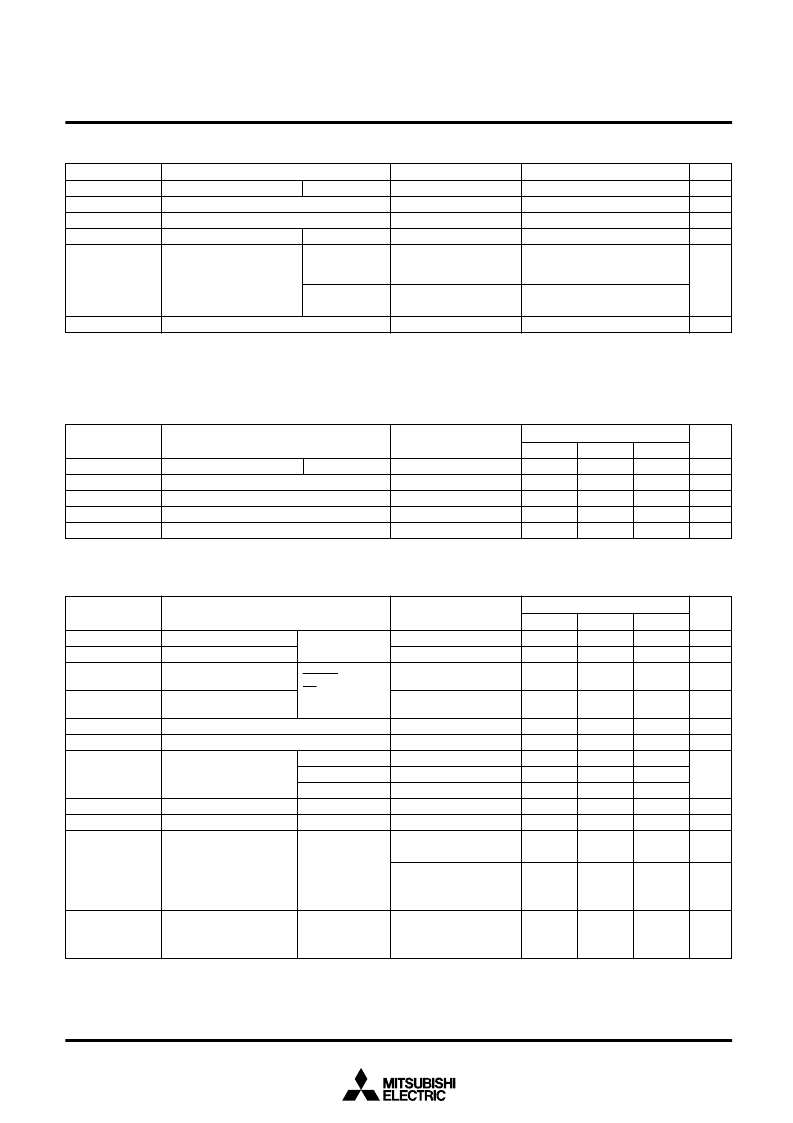
ABSOLUTE MAXIMUM RATINGS
Symbol
V
CC
V
P
V
I
V
O
Conditions
(Note 3)
Any external circuits are
not connected to the IC.
T
a
=25
°
C (Note 4)
The IC is mounted on a
board. T
a
=25
°
C (Note 5)
Ratings
–0.3 ~ + 7
V
CC
–45 ~ V
CC
+ 0.3
–0.3 ~ V
CC
+ 0.3
–0.3 ~ V
CC
+ 0.3
1.6
1.4
–65 ~ 150
P
d
T
stg
Parameter
Supply voltage
Pull-down voltage
Input voltage
Output voltage
Maximum power dissipation
Storage temperature
Unit
V
V
V
V
W
°
C
V
CC1
, V
CC2
X
OUT
, P0, P1
SP
FP
Notes 3: Frequency of pulse waveform exceeding V
CC
-40V:450
μ
s or above, pulse width: 30
μ
s or below, output load: C
L
≤
200pF
4: When T
a
is 25
°
C or above, derating (12.8mW/
°
C) should be conducted.
5: When T
a
is 25
°
C or above, derating (11.2mW/
°
C) should be conducted.
Unit
V
V
V
V
°
C
Symbol
V
CC
V
P
V
SS
V
I
T
opr
Parameter
Supply voltage
Pull-down voltage
Supply voltage
Input voltage
Operating temperature
Limits
Typ.
5
Min.
4.5
V
CC
–40
0
–10
0
Max.
5.5
V
CC
V
CC
70
V
CC1
, V
CC2
RECOMMENDED OPERATIONAL CONDITIONS
(T
a
=
–
10 ~ 70
°
C unless otherwise noted)
Conditions
SDATA
RESET
CS
SCK, X
IN
DIG output
SEG output
P0, P1
P0, P1
DIG, SEG
V
CC1
, V
CC2
V
P
Symbol
V
IH
V
IL
V
T+
V
T–
I
IH
I
IL
V
OH
V
OL
I
O
I
CC
I
P
Parameter
Limits
Typ.
Max.
0.3V
CC
0.7V
CC
0.55V
CC
1
–1
0.55
850
100
40
–40
Min.
0.7V
CC
0.35V
CC
0.2V
CC
V
CC
–2
V
CC
–2
V
CC
–0.8
250
Unit
V
V
V
V
μ
A
μ
A
V
V
μ
A
μ
A
mA
mA
DC CHARACTERISTICS
(T
a
= –10 ~ 70
°
C, V
CC
= 5V
±
10%, V
SS
= 0V)
2.8
2
500
Conditions
V
I
=V
CC
V
I
=0V
I
OH
=–20mA
I
OH
=–5mA
I
OH
=–2mA
I
OL
=2mA
V
P
=V
CC
–40V, V
O
=V
CC
V
I
=0V, Output pin: open
V
P
=V
CC
–40V
Output pin: open
Output “H”, clock stop
V
P
=V
CC
–40V
Output pin: open
Output “H”, clock stop
V
P
=V
CC
–40V
(Note 6)
“H” input voltage
“L” input voltage
Positive direction
threshold voltage
Negative direction
threshold voltage
“H” input current
“L” input current
“H” output voltage
“L” output voltage
Output pull-down current
Positive supply current
Negative supply current
Note 6: Total of current at pin V
CC1
and current at pin V
CC2
.
相關(guān)PDF資料 |
PDF描述 |
|---|---|
| M66006FP | 12-BIT I/O EXPANDER |
| M66006P | 12-BIT I/O EXPANDER |
| M66008 | 16-BIT I/O EXPANDER |
| M66008FP | 16-BIT I/O EXPANDER |
| M66008P | 16-BIT I/O EXPANDER |
相關(guān)代理商/技術(shù)參數(shù) |
參數(shù)描述 |
|---|---|
| M66005-0001AHP | 制造商:Renesas Electronics Corporation 功能描述: |
| M66006FP | 制造商:Panasonic Industrial Company 功能描述:IC |
| M66006P | 制造商:MITSUBISHI 制造商全稱:Mitsubishi Electric Semiconductor 功能描述:12-BIT I/O EXPANDER |
| M66007FP | 制造商:MITSUBISHI 制造商全稱:Mitsubishi Electric Semiconductor 功能描述:12-BIT INPUT EXPANDER |
| M66007P | 制造商:MITSUBISHI 制造商全稱:Mitsubishi Electric Semiconductor 功能描述:12-BIT INPUT EXPANDER |
發(fā)布緊急采購,3分鐘左右您將得到回復(fù)。