- 您現(xiàn)在的位置:買賣IC網(wǎng) > PDF目錄370984 > M61206FP (Mitsubishi Electric Corporation) NTSC TV SIGNAL PROCESSOR PDF資料下載
參數(shù)資料
| 型號: | M61206FP |
| 廠商: | Mitsubishi Electric Corporation |
| 英文描述: | NTSC TV SIGNAL PROCESSOR |
| 中文描述: | NTSC電視信號處理器 |
| 文件頁數(shù): | 33/51頁 |
| 文件大小: | 1306K |
| 代理商: | M61206FP |
第1頁第2頁第3頁第4頁第5頁第6頁第7頁第8頁第9頁第10頁第11頁第12頁第13頁第14頁第15頁第16頁第17頁第18頁第19頁第20頁第21頁第22頁第23頁第24頁第25頁第26頁第27頁第28頁第29頁第30頁第31頁第32頁當(dāng)前第33頁第34頁第35頁第36頁第37頁第38頁第39頁第40頁第41頁第42頁第43頁第44頁第45頁第46頁第47頁第48頁第49頁第50頁第51頁

NTSC TV SIGNAL PROCESSOR
M6120
6
FP
MITSUBISHI ICs (TV)
MITSUBISHI
ELECTRIC
GTmax : Video tone control characteristic 1
1. Input SG.B (f=2.5MHz) to pin 34.
2. The output amplitude at pins 14, 15 and 16 when video
tone data is center (20H) are defined as GTnor.
3. Measure output amplitude at pins 14, 15 and 16 at video
tone data maximum.
4. GTmax is defined as follows:
Measured value (mV
p-p
)
GTnor (mV
p-p
)
GTmax = 20 log
(dB)
FBY : Video frequency characteristics
1. Input SG.B (5MHz, 0.4V
p-p
) to pin 34.
2. Measure the amplitude (peak to peak) except measure
from blanking part of the output at pins 14, 15 and 16. The
amplitude is defined as YB.
3. FBY is defined as follows:
YB V
p-p
GY V
p-p
FBY = 20 log
(dB)
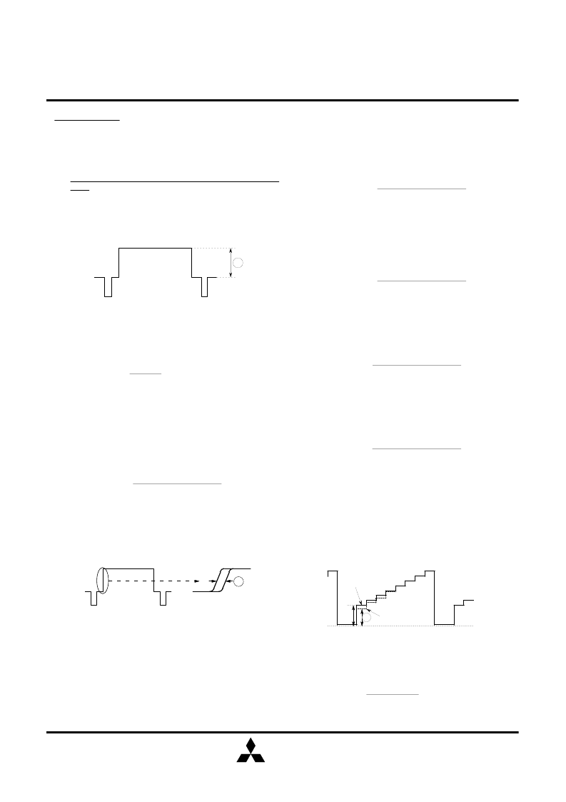
YDL1 : Y delay time 1
1. Input SGA to pin 34.
2. Measure the delay time from signal input to output at pins
14, 15 and 16.
M
SGA
Output signal
Measure the delay time at the center point of rise.
Ymax : Maximum video output
1. Input SG.A to pin 34.
2. Measure the amplitude (peak to peak) except measure
from blanking part of output at pins 14, 15 and 16.
M
VIDEO BLOCK
CRF : Chroma trap attenuation
(common to R/G/B output)
TRF : Chroma trap maximum attenuation
1. Input SG.C to pin 34. Measure the frequency level of
3.58MHz at trap on/off (02H D4) data 1. The level is defined
as N
0
.
2. Then, measure the level at trap on/off data 1 (trap active).
3. CRF is defined as follows.
CRF = 20 log
(dB)
Measured value (mV
p-p
)
N
0
(mV
p-p
)
4. TRF is minimum value of CRF at which I
2
C bus data of
Trap fine adj. (12H D0/D1) is adjusted.
2AGTV :Video SW output level (TV input)
2AGEV :Video SW output level (External input)
1. Input SG.A to pin 36 (2AGTV) or pin 34 (2AGEV).
2. Measure the amplitude (peak to peak) at pin 40.
Note : use sub address 06H to select TV or external video
input.
GTmin = 20 log
(dB)
Measured value (mV
p-p
)
GTnor (mV
p-p
)
GTmin : Video tone control characteristic 2
1. Input SG.B (f=2.5MHz) to pin 34.
2. The output amplitude at pins 14, 15 and 16 when video
tone data is center (20H) are defined as GTnor.
3. Measure output amplitude at pins 14, 15 and 16 at video
tone data minimum.
4. GTmin is defined as follows:
1. Input SG.A to pin 34.
2. Measure output amplitude when mute switch (02H D7) is
on "VMFon" and off "VMFoff".
3. VMF is defined as follows:
VMFon (V
p-p
)
VMFoff (V
p-p
)
VMF Video mute characteristics
VMF = 20 log
(dB)
GT1M : Video tone control characteristic 3
1. The output amplitude at pins 14, 15 and 16 when
frequency of input signal is 2.5MHz are defined as GTnor.
2. Input SG.B (f=2MHz) to pin 34.
3. Measure output amplitude at pins 14, 15 and 16.
4. GT2M is defined as follows:
Measured value (mV
p-p
)
GTnor (mV
p-p
)
GT2M = 20 log
(dB)
GT5M : Video tone control characteristic 4
1. The output amplitude at pins 14, 15 and 16 when
frequency of input signal is 2.5MHz are defined as GTnor.
2. Input SG.B (f=5MHz) to pin 34.
3. Measure output amplitude at pins 14, 15 and 16.
4. GT5M is defined as follows:
Measured value (mV
p-p
)
GTnor (mV
p-p
)
GT5M = 20 log
(dB)
YDL2, 3 and 4 : Y delay time 2, 3 and 4
1. Input SGA to pin 34.
2. Measure the delay time from signal input to output at pins
14, 15 and 16.
3. YDL2, YDL3 and YDL4 are defined as follows:
YDL2=Measured value (nsec) - YDL1
YDL3=Measured value (nsec) - YDL2
YDL4=Measured value (nsec) - YDL3
1. Input SG.K to pin 34.
2. At condition of Black stretch OFF (06H D3=1), set output
level of the first step (the lowest step) to 2.0V and eighth step
(the highest step) to 4.6V at pins 14, 15 and 16 by adjusting
Contrast (05H) and Brightness (0AH).
3. Change to Black stretch ON (06H D3=0), and measure the
output level of the first step at pins 14, 15 and 16.
4. BLS is defined as follows:
BLS Black stretch characteristics
0V
4.6V
2.0V
M
Black stretch OFF
Black stretch ON
BLS = 2.0 - Measured value (V)
33
相關(guān)PDF資料 |
PDF描述 |
|---|---|
| M61301SP | BUS CONTROLLED 3CH VIDEO PRE-AMP FOR CRT DISPLAY MONITOR |
| M61303FP | IIC BUS controled 3channel video pre-amplifier for LCD display monitor |
| M61314SP | I2C BUS CONTROLLED VIDEO PRE-AMP FOR HIGH RESOLUTION COLOR DISPLAY |
| M61323FP | WIDE FREQUENCY BAND ANALOG SWITCH |
| M61323SP | WIDE FREQUENCY BAND ANALOG SWITCH |
相關(guān)代理商/技術(shù)參數(shù) |
參數(shù)描述 |
|---|---|
| M6121-4007-A-24 | 功能描述:機架和機柜配件 Rnd Metric Hndl 38mm Alum Blk Anod RoHS:否 制造商:Bivar 產(chǎn)品:Rack Accessories 面板空間: 顏色:Black |
| M6121-4007-SS | 功能描述:機架和機柜配件 Rnd Metric Hndl 38mm 6.3 DIA S/S RoHS:否 制造商:Bivar 產(chǎn)品:Rack Accessories 面板空間: 顏色:Black |
| M6122-4007-A-24 | 功能描述:機架和機柜配件 Rnd Metric Hndl 44mm Alum Blk Anod RoHS:否 制造商:Bivar 產(chǎn)品:Rack Accessories 面板空間: 顏色:Black |
| M6122-4007-SS | 功能描述:機架和機柜配件 Rnd Metric Hndl 44mm 6.3 DIA S/S RoHS:否 制造商:Bivar 產(chǎn)品:Rack Accessories 面板空間: 顏色:Black |
| M6123-4007-A-24 | 功能描述:機架和機柜配件 Rnd Metric Hndl 51mm Alum Blk Anod RoHS:否 制造商:Bivar 產(chǎn)品:Rack Accessories 面板空間: 顏色:Black |
發(fā)布緊急采購,3分鐘左右您將得到回復(fù)。