- 您現(xiàn)在的位置:買賣IC網(wǎng) > PDF目錄370967 > M54678FP (Mitsubishi Electric Corporation) 2-PHASE STEPPER MOTOR DRIVER PDF資料下載
參數(shù)資料
| 型號(hào): | M54678FP |
| 廠商: | Mitsubishi Electric Corporation |
| 元件分類: | 基準(zhǔn)電壓源/電流源 |
| 英文描述: | 2-PHASE STEPPER MOTOR DRIVER |
| 中文描述: | 二相步進(jìn)電機(jī)驅(qū)動(dòng)器 |
| 文件頁(yè)數(shù): | 4/5頁(yè) |
| 文件大小: | 102K |
| 代理商: | M54678FP |
2-PHASE STEPPER MOTOR DRIVER
M54678FP
MITSUBISHI <CONTROL / DRIVER IC>
APPLICATION DIRECTIONS
(1) Ph input, En input determines output function.
(2) Vref (reference voltage)
Output current level is controlled by Vref voltage.
(3) Current comparator
Under VRS (current sensing resistor voltage) > Vref (reference
voltage) condition, the current comparator switches, fip-flop is
reset and output circuit is set to off.
(4) Oscillating circuit
Frequency of PWM operation synchronize with Fref terminal
frequency.
If you change frequency of PWM operation, please change
capacitor value of Fref terminal.
This IC is designed oscillating frequency to be 30kHz when
capacitor = 390pF is connected to Fref terminal. Oscillating
frequency is inversely proportional to capacitor value. When
capacitor value become half, Oscillating frequency will be two
times.
(5) Spike current cancellation circuit
This IC includes Spike cancellation circuit to prevent the failure
function of current comparator by influence of this spike current.
Thus, current comparator don’t function during approximately
2
μ
S from the moment of output transistor is set to on.
(6) Phase delay circuit
This IC includes Phase delay circuit to prevent output through
current at Ph switching time.
Four output transistors of H bridge don’t function during
approximately 3
μ
S at Ph switching time.
(7) Rs terminal and S terminal
Difference of current sensing that caused by wiring resistance
of board (wiring resistance between RS terminal and current
sensing resistor) can be prevented by connecting S terminal
(plus input of current comparator) to current sensing resistor as
close as possible.
(8) Voltage stabilizer circuit
This IC includes voltage stabilizer circuit. (3.5volts output). Vref
reference voltage can be generated by resistance potential
dividing from constant voltage output terminal (Regout). Current
capability of constant voltage output terminal is I source =
+1mA, I sink = -0.1mA
Ph*
H
L
H
L
En*
L
L
H
H
Out*
H
L
Z
Z
Out*B
L
H
Z
Z
*: 1 or 2
Z : High impedance
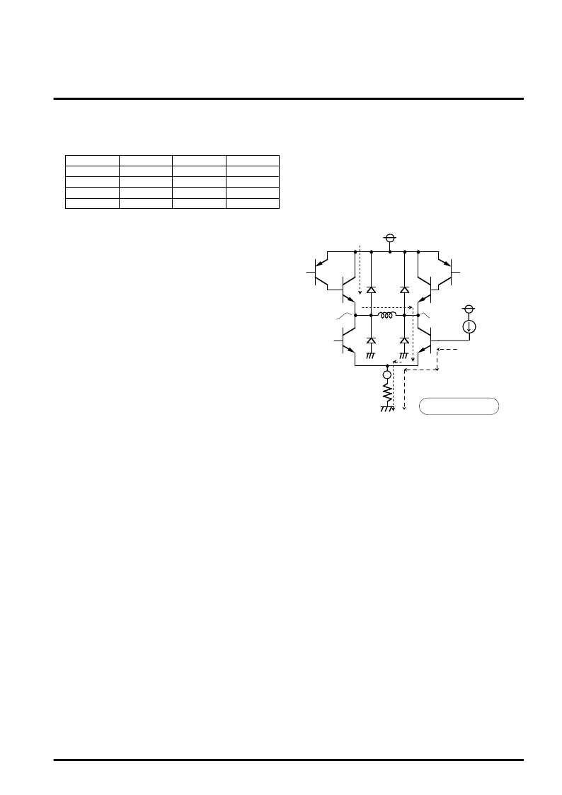
(9) Setting of output current
Since output circuit of this IC consists of NPN type transistor,
current flow through the motor coil (Iout) becomes
approximately 20mA (typical value) smaller than current flow
through the current sensing resistor (IRS) by influence of the
base current (Ib) of transistor.
Thus, please consider this current when you set up output
current.
OFF
ON
OFF
ON
RS
Iout
MB
MA
VM
V
CC
Ib = 10mA (Typ.)
Iout = IRS - Ib
*If Vcc, Tj and manufacturing dispersion are considered,
dispersion of Ib will vary maximum
±
5mA
(minimum = 5mA, maximum = 15mA)
相關(guān)PDF資料 |
PDF描述 |
|---|---|
| M54685L | CAPACITOR ROHS 200V, 7400 UF |
| M54687FP | Bi-DIRECTIONAL MOTOR DRIVER WITH GOVERNOR |
| M54910P | F2F MAGNETIC STRIPE ENCORDING CARD READER |
| M54914FP | F2F MAGNETIC STRIPE ENCORDING CARD READER |
| M54965ASP | SERIAL INPUT PLL FREQUENCY SYNTHESIZER FOR VTR |
相關(guān)代理商/技術(shù)參數(shù) |
參數(shù)描述 |
|---|---|
| M54679FP | 制造商:MITSUBISHI 制造商全稱:Mitsubishi Electric Semiconductor 功能描述:2-PHASE STEPPER MOTOR DRIVER |
| M54679SP | 制造商:HITACHI 制造商全稱:Hitachi Semiconductor 功能描述:2-Phase Stepper Motor Driver |
| M54679SP(#TB0G) | 制造商:Renesas Electronics Corporation 功能描述: |
| M54685L | 制造商:MITSUBISHI 制造商全稱:Mitsubishi Electric Semiconductor 功能描述:Bi-DIRECTIONAL MOTOR DRIVER WITH GOVERNOR |
| M54687FP | 制造商:RENESAS 制造商全稱:Renesas Technology Corp 功能描述:Bi-Directional Motor Driver with Governor |
發(fā)布緊急采購(gòu),3分鐘左右您將得到回復(fù)。