- 您現(xiàn)在的位置:買賣IC網(wǎng) > PDF目錄384639 > M52744SP (Mitsubishi Electric Corporation) I 2 C BUS CONTROLLED 3-CHANNEL VIDEO PREAMPLIFIER PDF資料下載
參數(shù)資料
| 型號(hào): | M52744SP |
| 廠商: | Mitsubishi Electric Corporation |
| 英文描述: | I 2 C BUS CONTROLLED 3-CHANNEL VIDEO PREAMPLIFIER |
| 中文描述: | 的I 2 C總線控制的三通道視頻前置放大器 |
| 文件頁(yè)數(shù): | 6/19頁(yè) |
| 文件大小: | 136K |
| 代理商: | M52744SP |
第1頁(yè)第2頁(yè)第3頁(yè)第4頁(yè)第5頁(yè)當(dāng)前第6頁(yè)第7頁(yè)第8頁(yè)第9頁(yè)第10頁(yè)第11頁(yè)第12頁(yè)第13頁(yè)第14頁(yè)第15頁(yè)第16頁(yè)第17頁(yè)第18頁(yè)第19頁(yè)
MITSUBISHI ICs (Monitor)
M52743SP/M52744SP
I
2
C BUS CONTROLLED 3-CHANNEL VIDEO PREAMPLIFIER
6
ELECTRICAL CHARACTERISTICS
(cont.)
Symbol
Parameter
Test
point
(s)
Input
CTL
voltage
30
Bri-
ght
BUS CTL (H)
Limits
Unit
2,6,11
RGB
in
1
OSD
BLK
4,9,13
OSD
in
19
CP in
27
ReT
BLK
7
SOG
in
15
ABL
00H
Main
cont
01H
Sub
cont
1
02H
Sub
cont
2
03H
Sub
cont
3
04H
OSD
Adj
05H
BLK
Adj
06H
D/A
OUT
1
07H
D/A
OUT
2
08H
D/A
OUT
3
09H
D/A
OUT
4
0BH
INT
Min. Typ. Max.
TDS-R
Sync output
delay time2
D/A H output
voltage
D/A L output
voltage
D/A output
current range
D/A
nonlinearity
Sync
OUT
D/A
OUT
D/A
OUT
D/A
OUT
D/A
OUT
a
a
a
a
a
b
SG4
2.0 5.0
0 60 90
ns
VOH
a
a
a
a
a
a
2.0 5.0
FFH
255
FFH
255
FFH
255
FFH
255
00H
0
00H
0
FFH
255
FFH
255
FFH
255
FFH
255
00H
0
4.5 5.0 5.5
VDC
VOL
a
a
a
a
a
a
2.0 5.0
00H
0
00H
0
00H
0
00H
0
0 0.5 1.0
VDC
IAO
a
a
a
a
a
a
2.0 5.0
abl
e
abl
e
abl
e
abl
e
-1.0
0.4
mA
DNL
a
a
a
a
a
a
2.0 5.0
abl
e
abl
e
abl
e
abl
e
-1.0
1.0
LSB
ELECTRICAL CHARACTERISTICS TEST METHOD
I
CC1
Circuit current1
Measuring conditions are as listed in supplementary Table.
Mesured with a current meter at test point IA.
I
CC2
Circuit current2
Measureing conditions are as listed in supplemtary Table.
Measured with a current meter at test point IB.
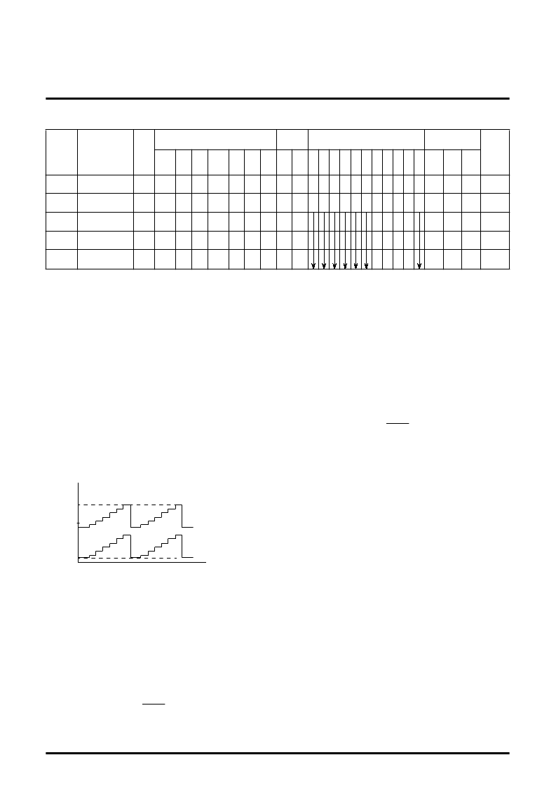
Vomax Output dynamic range
Decrease V30 gradually, and measure the voltage when the bottom
of waveform output is distorted. The voltage is called VCL.
Next, increase V30 gradually, and measure the voltage when the
top of waveform output is distorted. The voltage is called VOH.
Voltage Vomax is calculated by the equation below:
Vomax = VOH-VOL
(V)
Vimax Maximum input
Increase the input signal (SG2) amplitude gradually, starting from
700mV
P-P
. Measure the amplitude of the input signal when the
output signal starts becoming distorted.
Gv Maximum gain
Input SG1, and read the amplitude output at OUT (29, 32, 35). The
amplitude is called VOUT (29, 32, 35). Maximum gain G
V
is
calculated by the equation below:
0.7
Gv Relative maximum gain
Relative maximum gain
G
V
is calculated by the equation bellow:
G
V
= VOUT (29)/VOUT (32),
VOUT (32)/VOUT (35),
VOUT (35)/VOUT (29)
V
C1
Main contrast control characteristics1
Measureing the amplitude output at OUT (29, 32, 35). The
measured value is called VOUT (29, 32, 35). Main contrast control
characterics V
C1
is calculated by the equation bellow:
0.7
V
C1
Main contrast control relative characteristics1
Relative characteristics
V
C1
is calculated by the equation bellow:
V
C1
=VOUT (29)/VOUT (32),
VOUT (32)/VOUT (35),
VOUT (35)/VOUT (29)
V
C2
Main contrast control characteristics2
Measuring condition and procedure are the same as described in
V
C1
.
V
C2
Main contrast control relative characteristics2
Measuring condition and procedure are the same as described in
V
C1
.
V
C3
Main contrast control characteristics3
Measuring condition and procedure are the same as described in
V
C1
.
V
C3
Main contrast control relative characteristics3
Measuring condition and procedure are the same as described in
V
C1
.
5.0
Waveform output
VOH
VOL
0.0
G
V
=20Log VOUT
V
C1
=20Log VOUT
相關(guān)PDF資料 |
PDF描述 |
|---|---|
| M52766FP | PLL SPLIT VIF / SIF |
| M52780-XXXSP | I2C BUS CONTROLLED 3CH VIDEO PRE-AMP WITH OSD CONTROLLER FOR HIGH RESOLUTION COLOR DISPLAY MONITOR |
| M54519FP | 7-UNIT 400mA DARLINGTON TRANSISTOR ARRAY |
| M54519P | 7-UNIT 400mA DARLINGTON TRANSISTOR ARRAY |
| M54519 | 7-UNIT 400mA DARLINGTON TRANSISTOR ARRAY |
相關(guān)代理商/技術(shù)參數(shù) |
參數(shù)描述 |
|---|---|
| M52745SP | 制造商:Panasonic Industrial Company 功能描述:IC |
| M52746SP | 制造商:MITSUBISHI 制造商全稱:Mitsubishi Electric Semiconductor 功能描述:BUS CONTROLLED 3CH VIDEO PRE-AMP FOR CRT DISPLAY MONITOR |
| M52749FP | 制造商:RENESAS 制造商全稱:Renesas Technology Corp 功能描述:BUS Controlled 3ch Video Pre-amp for CRT Display Monitor |
| M527534-12 | 制造商:ITT 制造商全稱:ITT Industries 功能描述:Cannon MIL-DTL-38999 Connectors |
| M52755FP | 制造商:MITSUBISHI 制造商全稱:Mitsubishi Electric Semiconductor 功能描述:WIDE BAND ANALOG SWITCH |
發(fā)布緊急采購(gòu),3分鐘左右您將得到回復(fù)。