- 您現(xiàn)在的位置:買賣IC網(wǎng) > PDF目錄359067 > M48T59Y-70PC1TR (意法半導(dǎo)體) 64 Kbit 8Kb x8 TIMEKEEPER SRAM PDF資料下載
參數(shù)資料
| 型號: | M48T59Y-70PC1TR |
| 廠商: | 意法半導(dǎo)體 |
| 英文描述: | 64 Kbit 8Kb x8 TIMEKEEPER SRAM |
| 中文描述: | 64千位8KB的x8 SRAM的計(jì)時(shí)器 |
| 文件頁數(shù): | 4/17頁 |
| 文件大小: | 135K |
| 代理商: | M48T59Y-70PC1TR |
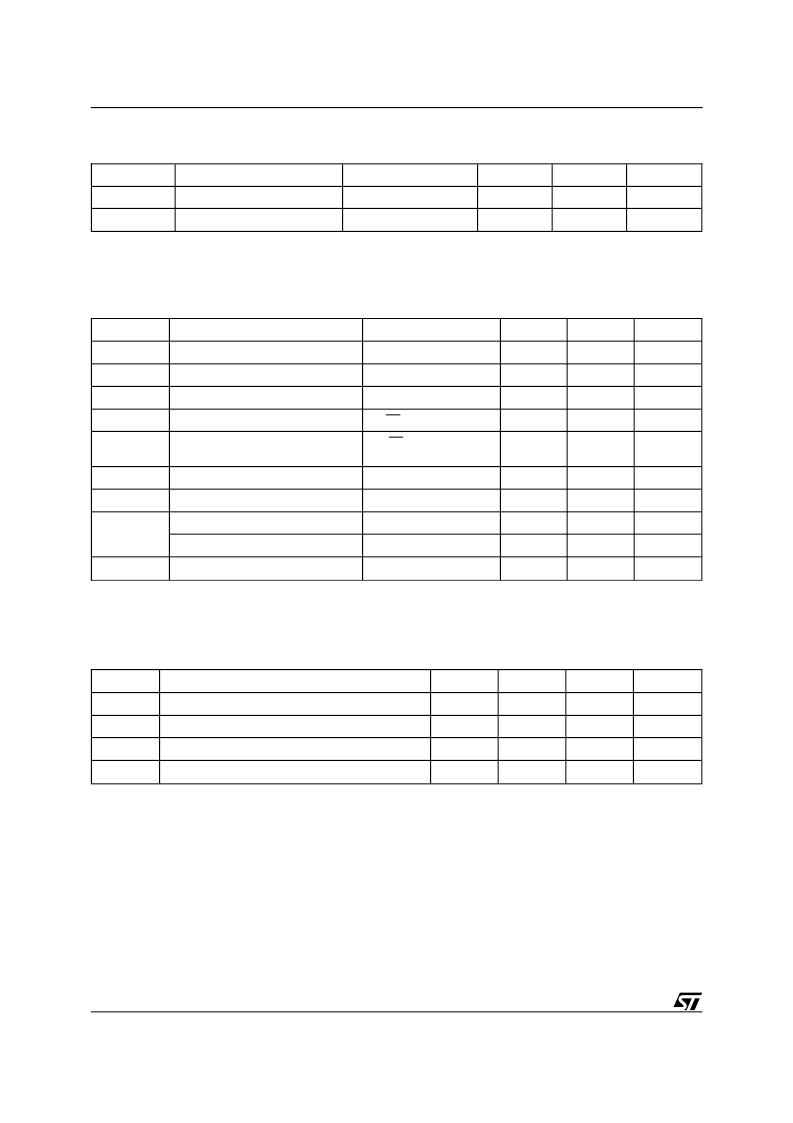
Symbol
Parameter
Test Condition
Min
Max
Unit
I
LI (1)
Input Leakage Current
0V
≤
V
IN
≤
V
CC
±
1
μ
A
I
LO (1)
Output Leakage Current
0V
≤
V
OUT
≤
V
CC
±
5
μ
A
I
CC
Supply Current
Outputs open
50
mA
I
CC1
Supply Current (Standby) TTL
E1 = V
IH
, E2 = V
IL
3
mA
I
CC2
Supply Current (Standby) CMOS
E1 = V
CC
– 0.2V,
E2 = V
SS
+ 0.2V
3
mA
V
IL (2)
Input Low Voltage
–0.3
0.8
V
V
IH
Input High Voltage
2.2
V
CC
+ 0.3
V
V
OL
Output Low Voltage
I
OL
= 2.1mA
0.4
V
Output Low Voltage (FT)
(3)
I
OL
= 10mA
0.4
V
V
OH
Output High Voltage
I
OH
= –1mA
2.4
V
Notes:
1. Outputs Deselected.
2. Negative spikes of –1V allowed for up to 10ns once per Cycle.
3. The FT pin is Open Drain.
Table 6. DC Characteristics
(T
A
= 0 to 70
°
C; V
CC
= 4.75V to 5.5V or 4.5V to 5.5V)
Symbol
Parameter
Test Condition
Min
Max
Unit
C
IN
C
IO (3)
Input Capacitance
V
IN
= 0V
10
pF
Input / Output Capacitance
V
OUT
= 0V
10
pF
Notes:
1. Effective capacitance measured with power supply at 5V.
2. Sampled only, not 100% tested.
3. Outputs deselected
Table 5. Capacitance
(1, 2)
(T
A
= 25
°
C, f = 1 MHz )
Symbol
Parameter
Min
Typ
Max
Unit
V
PFD
Power-fail Deselect Voltage (M48T58)
4.5
4.6
4.75
V
V
PFD
Power-fail Deselect Voltage (M48T58Y)
4.2
4.35
4.5
V
V
SO
Battery Back-up Switchover Voltage
3.0
V
t
DR(2)
Expected Data Retention Time
7
YEARS
Notes:
1. All voltages referenced to V
SS
.
2. At 25°C
Table 7. Power Down/Up Trip Points DC Characteristics
(1)
(T
A
= 0 to 70
°
C)
For the 28 lead SOIC, the battery/crystal package
(i.e. SNAPHAT) part number is "M4T28-
BR12SH1".
As Figure 3 shows, the static memory array and the
quartz controlled clock oscillator of the
M48T58/58Y are integrated on one silicon chip.
The two circuits are interconnected at the upper
eight memory locations to provide user accessible
BYTEWIDE
clock information in the bytes with
addresses 1FF8h-1FFFh. The clock locations con-
tain the year, month, date, day, hour, minute, and
second in 24 hour BCD format. Corrections for 28,
29 (leap year), 30, and 31 day months are made
automatically. Byte 1FF8h is the clock control reg-
ister. This byte controls user access to the clock
information and also stores the clock calibration
setting.
DESCRIPTION
(cont’d)
4/17
M48T58, M48T58Y
相關(guān)PDF資料 |
PDF描述 |
|---|---|
| M48TMH1 | 5V PC REAL TIME CLOCK |
| M48TMH1TR | 5V PC REAL TIME CLOCK |
| M48TY-85MH1 | 3.3V-5V TIMEKEEPER CONTROLLER |
| M48TY-85MH1TR | 3.3V-5V TIMEKEEPER CONTROLLER |
| M48TY-85PM1 | 3.3V-5V 1 Mbit 128Kb x8 TIMEKEEPER SRAM |
相關(guān)代理商/技術(shù)參數(shù) |
參數(shù)描述 |
|---|---|
| M48T59Y-70PC6 | 制造商:STMICROELECTRONICS 制造商全稱:STMicroelectronics 功能描述:64 Kbit 8Kb x8 TIMEKEEPER SRAM |
| M48T59Y-70PC6TR | 制造商:STMICROELECTRONICS 制造商全稱:STMicroelectronics 功能描述:64 Kbit 8Kb x8 TIMEKEEPER SRAM |
| M48T59YMH | 制造商:STMICROELECTRONICS 制造商全稱:STMicroelectronics 功能描述:64 Kbit 8Kb x8 TIMEKEEPER SRAM |
| M48T59YPC | 制造商:STMICROELECTRONICS 制造商全稱:STMicroelectronics 功能描述:64 Kbit 8Kb x8 TIMEKEEPER SRAM |
| M48T59YSH | 制造商:STMICROELECTRONICS 制造商全稱:STMicroelectronics 功能描述:64 Kbit 8Kb x8 TIMEKEEPER SRAM |
發(fā)布緊急采購,3分鐘左右您將得到回復(fù)。