- 您現(xiàn)在的位置:買賣IC網(wǎng) > PDF目錄45050 > M48ST59W-100MH1 (STMICROELECTRONICS) 0 TIMER(S), REAL TIME CLOCK, PDSO44 PDF資料下載
參數(shù)資料
| 型號(hào): | M48ST59W-100MH1 |
| 廠商: | STMICROELECTRONICS |
| 元件分類: | 時(shí)鐘/數(shù)據(jù)恢復(fù)及定時(shí)提取 |
| 英文描述: | 0 TIMER(S), REAL TIME CLOCK, PDSO44 |
| 封裝: | 0.330 INCH, SNAPHAT, PLASTIC, SOH-44 |
| 文件頁(yè)數(shù): | 13/29頁(yè) |
| 文件大?。?/td> | 158K |
| 代理商: | M48ST59W-100MH1 |
第1頁(yè)第2頁(yè)第3頁(yè)第4頁(yè)第5頁(yè)第6頁(yè)第7頁(yè)第8頁(yè)第9頁(yè)第10頁(yè)第11頁(yè)第12頁(yè)當(dāng)前第13頁(yè)第14頁(yè)第15頁(yè)第16頁(yè)第17頁(yè)第18頁(yè)第19頁(yè)第20頁(yè)第21頁(yè)第22頁(yè)第23頁(yè)第24頁(yè)第25頁(yè)第26頁(yè)第27頁(yè)第28頁(yè)第29頁(yè)
M48ST59W
20/29
If a battery low indication is generated during the
24-hour interval check, this indicates that the bat-
tery is near end of life. However, data has not been
compromised due to the fact that a nominal VCC is
supplied. In order to insure data integrity during
subsequent periods of battery back-up mode, it is
recommended that the battery be replaced. The
SNAPHAT top may be replaced while VCC is ap-
plied to the device.
Note: This will cause the clock to lose time during
the interval the SNAPHAT battery/crystal top is
disconnected.
Note: Battery monitoring is a useful technique only
when performed periodically. The M48ST59W
only monitors the battery when a nominal VCC is
applied to the device. Thus applications which re-
quire extensive durations in the battery back-up
mode should be powered-up periodically (at least
once every few months) in order for this technique
to be beneficial. Additionally, if a battery low is in-
dicated, data integrity should be verified upon
power-up via a checksum or other technique.
Century Bit
Bits D5 and D4 of Clock Register 1FFCh contain
the CENTURY ENABLE Bit (CEB) and the CEN-
TURY Bit (CB). Setting CEB to a ’1’ will cause CB
to toggle, either from a ’0’ to ’1’ or from ’1’ to ’0’ at
the turn of the century (depending upon its initial
state). If CEB is set to a ’0,’ CB will not toggle.
Note: The WRITE Bit must be set in order to write
to the CENTURY Bit.
Initial Power-On Defaults
Upon application of power to the device, the fol-
lowing register bits are set to a ’0’ state: WDS;
BMB0-BMB4; RB0-RB1; AFE; ABE; W; R; and FT
(see Table 14):
TREC Bit
Bit D7 of Clock Register 1FFCh contains the
TREC Bit (TR). TREC refers to the automatic con-
tinuation of the deselect time after VCC reaches
VPFD (max). This allows for a voltage settling time
before WRITEs may again be performed to the de-
vice after a power-down condition. The TREC Bit
will allow the user to set the length of this deselect
time as defined by Table 13.
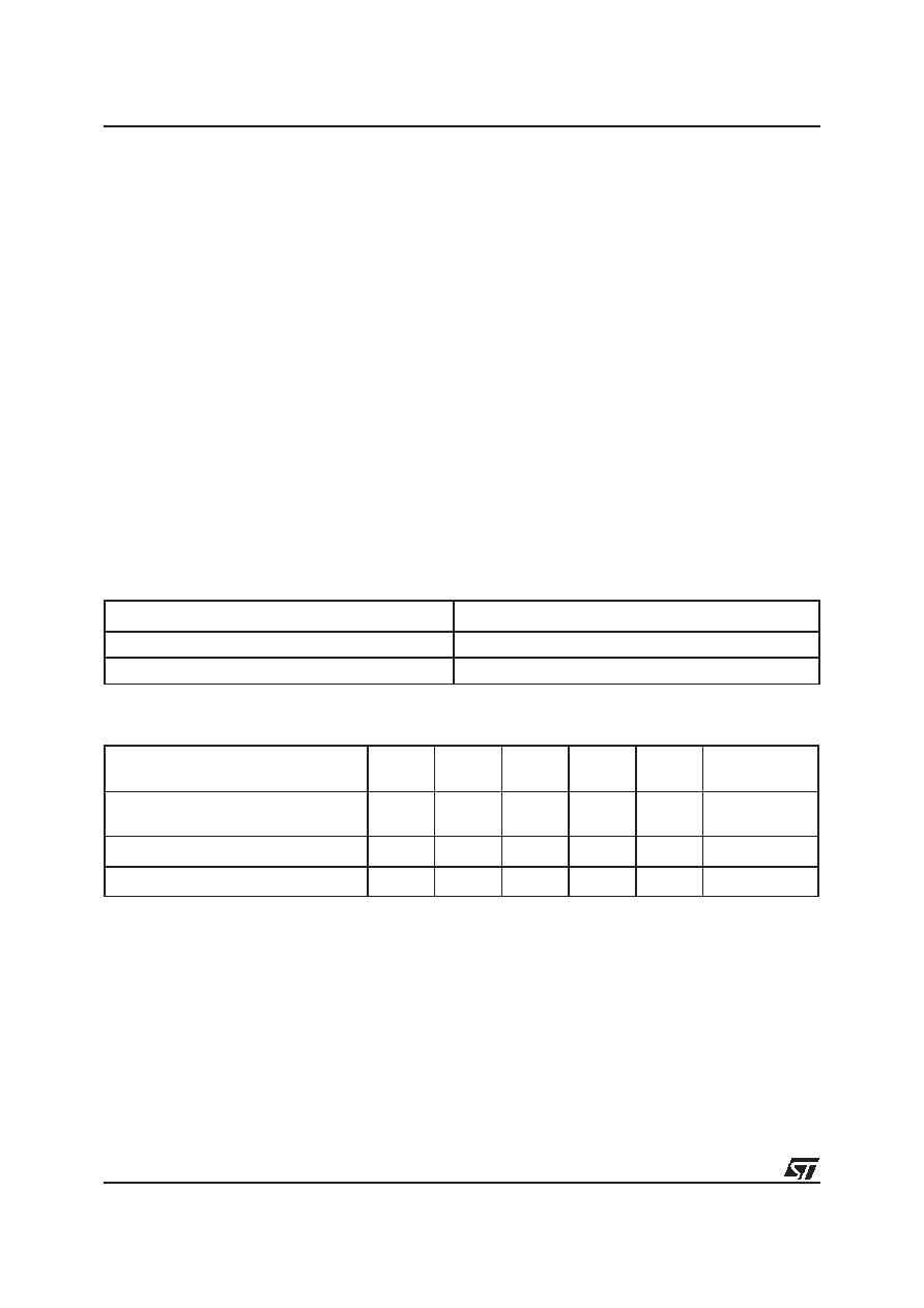
Table 13. tREC Definitions POWER-ON
Note: 1. Initial default is undefined.
Table 14. Default Values
Note: 1. WDS, BMB0-BMB4, RBO, RB1.
2. State of other control bits undefined.
3. State of other control bits remains unchanged.
4. Assuming these bits set to ’1’ prior to power-down.
TREC Bit (TR)
tREC Time
(1)
0
40 ms to 200 ms
1
2 ms (max)
Condition
W
R
FT
AFE
ABE
WATCHDOG(1)
Register
Initial Power-up
(Battery Attach for SNAPHAT)(2)
00000
0
Subsequent Power-up / RESET(3)
00000
0
Power-down(4)
00011
0
相關(guān)PDF資料 |
PDF描述 |
|---|---|
| M48T02-150PC1 | 0 TIMER(S), REAL TIME CLOCK, PDIP24 |
| M48T18-100MH1TR | 0 TIMER(S), REAL TIME CLOCK, PDSO28 |
| M48T18-100MH1 | 0 TIMER(S), REAL TIME CLOCK, PDSO28 |
| M48T18-150PC1 | 0 TIMER(S), REAL TIME CLOCK, PDIP28 |
| M48T08-100PC1 | 0 TIMER(S), REAL TIME CLOCK, PDIP28 |
相關(guān)代理商/技術(shù)參數(shù) |
參數(shù)描述 |
|---|---|
| M48T02 | 制造商:STMICROELECTRONICS 制造商全稱:STMicroelectronics 功能描述:5.0V, 16 Kbit (2Kb x 8) TIMEKEEPER SRAM |
| M48T02_03 | 制造商:STMICROELECTRONICS 制造商全稱:STMicroelectronics 功能描述:5.0V, 16 Kbit (2Kb x 8) TIMEKEEPER㈢ SRAM |
| M48T02_07 | 制造商:STMICROELECTRONICS 制造商全稱:STMicroelectronics 功能描述:5.0V, 16 Kbit (2Kb x 8) TIMEKEEPER SRAM |
| M48T02_10 | 制造商:STMICROELECTRONICS 制造商全稱:STMicroelectronics 功能描述:5.0 V, 16 Kbit (2 Kb x 8) TIMEKEEPER? SRAM |
| M48T02-120PC1 | 制造商:STMICROELECTRONICS 制造商全稱:STMicroelectronics 功能描述:CMOS 8K x 8 TIMEKEEPER SRAM |
發(fā)布緊急采購(gòu),3分鐘左右您將得到回復(fù)。