- 您現(xiàn)在的位置:買賣IC網(wǎng) > PDF目錄98007 > M38C13M6-XXXFP 8-BIT, MROM, 4 MHz, MICROCONTROLLER, PQFP64 PDF資料下載
參數(shù)資料
| 型號: | M38C13M6-XXXFP |
| 元件分類: | 微控制器/微處理器 |
| 英文描述: | 8-BIT, MROM, 4 MHz, MICROCONTROLLER, PQFP64 |
| 封裝: | 14 X 14 MM, 0.80 MM PITCH, PLASTIC, LQFP-64 |
| 文件頁數(shù): | 25/61頁 |
| 文件大小: | 665K |
| 代理商: | M38C13M6-XXXFP |
第1頁第2頁第3頁第4頁第5頁第6頁第7頁第8頁第9頁第10頁第11頁第12頁第13頁第14頁第15頁第16頁第17頁第18頁第19頁第20頁第21頁第22頁第23頁第24頁當(dāng)前第25頁第26頁第27頁第28頁第29頁第30頁第31頁第32頁第33頁第34頁第35頁第36頁第37頁第38頁第39頁第40頁第41頁第42頁第43頁第44頁第45頁第46頁第47頁第48頁第49頁第50頁第51頁第52頁第53頁第54頁第55頁第56頁第57頁第58頁第59頁第60頁第61頁
Rev.2.40
Jun 14, 2004
page 29 of 56
38C1 Group
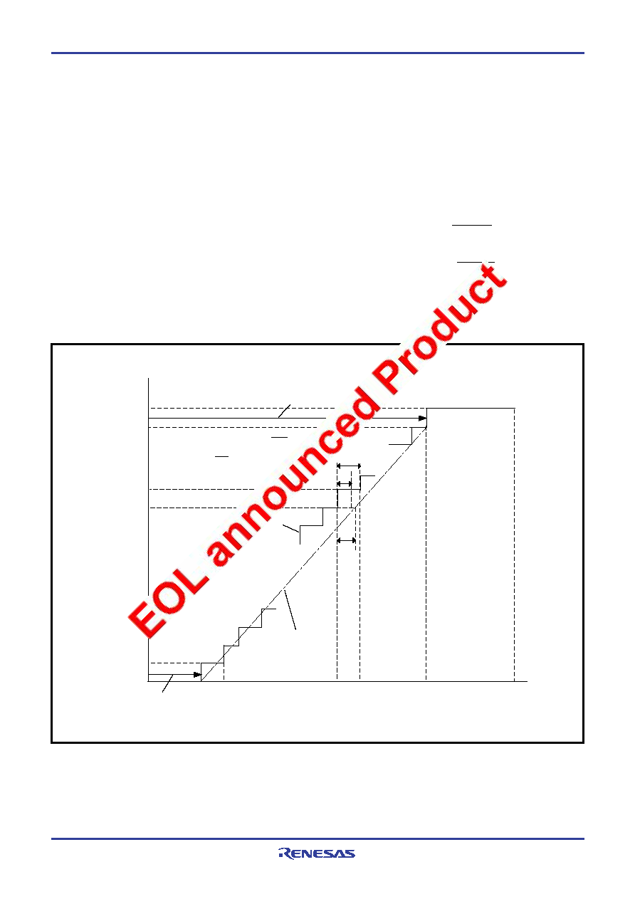
Definition of A/D converter accuracy
The A/D conversion accuracy is defined below (refer to Figure 28).
Relative accuracy
Zero transition voltage (V0T)
This means an analog input voltage when the actual A/D conver-
sion output data changes from “0” to “1.”
Full-scale transition voltage (VFST)
This means an analog input voltage when the actual A/D conver-
sion output data changes from “255” to ”254.”
Linearity error
This means a deviation from the line between V0T and VFST of a
converted value between V0T and VFST.
Differential non-linearity error
This means a deviation from the input potential difference re-
quired to change a converter value between V0T and VFST by 1
LSB at the relative accuracy.
Absolute accuracy
This means a deviation from the ideal characteristics between 0 to
VREF (VCC in 38C1 Group) of actual A/D conversion characteristics.
VREF
(VCC)
V254
Vn
V1
V0
Vn+1
n+1
n
254
255
1
0
b
a
c
Output data
Differential non-linearity error =
Linearity error =
[LSB]
c
a
b–a
a
[LSB]
Actual A/D conversion
characteristics
a: 1LSB by relative accuracy
b: Vn+1–Vn
c: Difference between ideal Vn
and actual Vn
Zero transition voltage (V0T)
Analog voltage
Full-scale transition voltage (VFST)
Ideal line of A/D conversion
between V0–V254
Fig. 28 Definition of A/D conversion accuracy
VFST–V0T
254
VREF*
256
Vn: Analog input voltage when the output data changes from “n” to
“n+1” (n = 0 to 254)
1LSB at relative accuracy
→
(V)
1LSB at absolute accuracy
→
(V)
* VREF = VCC in the 38C1 Group.
相關(guān)PDF資料 |
PDF描述 |
|---|---|
| M38C13M6-XXXHP | 8-BIT, MROM, 4 MHz, MICROCONTROLLER, PQFP64 |
| M38C59MF-XXXHP | 8-BIT, MROM, 6.25 MHz, MICROCONTROLLER, PQFP80 |
| M38K27M4-XXXHP | 8-BIT, MROM, 8 MHz, MICROCONTROLLER, PQFP64 |
| M41ST87WMX6T | 1 TIMER(S), REAL TIME CLOCK, PDSO28 |
| M41T00SC64MY6E | REAL TIME CLOCK, PDSO18 |
相關(guān)代理商/技術(shù)參數(shù) |
參數(shù)描述 |
|---|---|
| M38C13RLFS | 制造商:Renesas Electronics Corporation 功能描述:EMULATION MCU/8BIT CMOS EMULATION CHIP - Bulk |
| M38C24M4-XXXFP | 制造商:MITSUBISHI 制造商全稱:Mitsubishi Electric Semiconductor 功能描述:SINGLE-CHIP 8-BIT CMOS MICROCOMPUTER |
| M38C24M4-XXXHP | 制造商:MITSUBISHI 制造商全稱:Mitsubishi Electric Semiconductor 功能描述:SINGLE-CHIP 8-BIT CMOS MICROCOMPUTER |
| M38C24M6-051HP | 制造商:MITSUBISHI 制造商全稱:Mitsubishi Electric Semiconductor 功能描述:SINGLE-CHIP 8-BIT CMOS MICROCOMPUTER |
| M38C24M6-XXXFP | 制造商:MITSUBISHI 制造商全稱:Mitsubishi Electric Semiconductor 功能描述:SINGLE-CHIP 8-BIT CMOS MICROCOMPUTER |
發(fā)布緊急采購,3分鐘左右您將得到回復(fù)。