- 您現(xiàn)在的位置:買賣IC網 > PDF目錄370917 > M38277MBMXXXGP (Mitsubishi Electric Corporation) SINGLE-CHIP 8-BIT CMOS MICROCOMPUTER PDF資料下載
參數(shù)資料
| 型號: | M38277MBMXXXGP |
| 廠商: | Mitsubishi Electric Corporation |
| 英文描述: | SINGLE-CHIP 8-BIT CMOS MICROCOMPUTER |
| 中文描述: | 單芯片8位CMOS微機 |
| 文件頁數(shù): | 52/70頁 |
| 文件大小: | 1112K |
| 代理商: | M38277MBMXXXGP |
第1頁第2頁第3頁第4頁第5頁第6頁第7頁第8頁第9頁第10頁第11頁第12頁第13頁第14頁第15頁第16頁第17頁第18頁第19頁第20頁第21頁第22頁第23頁第24頁第25頁第26頁第27頁第28頁第29頁第30頁第31頁第32頁第33頁第34頁第35頁第36頁第37頁第38頁第39頁第40頁第41頁第42頁第43頁第44頁第45頁第46頁第47頁第48頁第49頁第50頁第51頁當前第52頁第53頁第54頁第55頁第56頁第57頁第58頁第59頁第60頁第61頁第62頁第63頁第64頁第65頁第66頁第67頁第68頁第69頁第70頁
52
SINGLE-CHIP 8-BIT CMOS MICROCOMPUTER
3827 Group
MITSUBISHI MICROCOMPUTERS
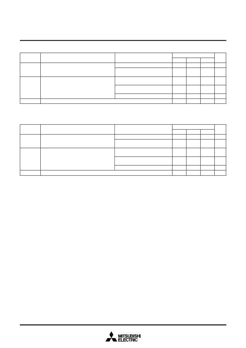
Table 14 Recommended operating conditions (Mask ROM version)
(V
CC
= 2.2 to 5.5 V, Ta = –20 to 85
°
C, unless otherwise noted)
Notes1:
When the oscillation frequency has a duty cycle of 50%.
2:
When using the microcomputer in low-speed mode, make sure that the sub-clock input oscillation frequency on condition that f(X
CIN
) < f(X
IN
)/3.
Input frequency for timers X and Y
(duty cycle 50%)
f(CNTR
0
)
f(CNTR
1
)
Symbol
Parameter
Limits
Typ.
Min.
MHz
Unit
Max.
4.0
(10
V
CC
–4)/9
(4.0 V
≤
V
CC
≤
5.5 V)
32.768
Main clock input oscillation frequency
(Note 1)
Sub-clock input oscillation frequency
(Notes 1, 2)
f(X
IN
)
f(X
CIN
)
(2.2 V
≤
V
CC
≤
4.0 V)
High-speed mode
(4.0 V
≤
V
CC
≤
5.5 V)
High-speed mode
(2.2 V
≤
V
CC
≤
4.0 V)
Middle-speed mode
8.0
(20
V
CC
–8)/9
8.0
50
MHz
MHz
MHz
MHz
kHz
Table 15 Recommended operating conditions (PROM version)
(V
CC
= 2.5 to 5.5 V, Ta = –20 to 85
°
C, unless otherwise noted)
Notes1:
When the oscillation frequency has a duty cycle of 50%.
2:
When using the microcomputer in low-speed mode, make sure that the sub-clock input oscillation frequency on condition that f(X
CIN
) < f(X
IN
)/3.
Input frequency for timers X and Y
(duty cycle 50%)
f(CNTR
0
)
f(CNTR
1
)
Symbol
Parameter
Limits
Typ.
Min.
MHz
Unit
Max.
4.0
(2
V
CC
)
(4.0 V
≤
V
CC
≤
5.5 V)
32.768
Main clock input oscillation frequency
(Note 1)
Sub-clock input oscillation frequency
(Notes 1, 2)
f(X
IN
)
f(X
CIN
)
(2.5 V
≤
V
CC
≤
4.0 V)
High-speed mode
(4.0 V
≤
V
CC
≤
5.5 V)
High-speed mode
(2.5 V
≤
V
CC
≤
4.0 V)
Middle-speed mode
–4
8.0
(4
V
CC
)
–8
8.0
50
MHz
MHz
MHz
MHz
kHz
Test conditions
Test conditions
相關PDF資料 |
PDF描述 |
|---|---|
| M38277MBMXXXHP | SINGLE-CHIP 8-BIT CMOS MICROCOMPUTER |
| M38270MCMXXXFP | BEADED TIE 12.75 NYLON |
| M38271MCMXXXFP | BEADED TIE 4 NYLON |
| M38272MCMXXXFP | BEADED TIE 5 NYLON |
| M38273MCMXXXFP | BEADED TIE 6 NYLON |
相關代理商/技術參數(shù) |
參數(shù)描述 |
|---|---|
| M3828 BK001 | 制造商:Alpha Wire Company 功能描述:CBL 3COND 16AWG BLK 1000' |
| M3828 BK002 | 制造商:Alpha Wire Company 功能描述:CBL 3COND 16AWG BLK 500' |
| M3828 BK005 | 制造商:Alpha Wire Company 功能描述:CBL 3COND 16AWG BLK 100' |
| M3828 BK199 | 制造商:Alpha Wire Company 功能描述:CBL 3COND 16AWG BLK 3000=3000' |
| M3829 BK001 | 制造商:Alpha Wire Company 功能描述:CBL 4COND 16AWG BLK 1000' |
發(fā)布緊急采購,3分鐘左右您將得到回復。