- 您現(xiàn)在的位置:買賣IC網(wǎng) > PDF目錄45037 > M37905F8CSP 16-BIT, FLASH, 20 MHz, MICROCONTROLLER, PDIP64 PDF資料下載
參數(shù)資料
| 型號(hào): | M37905F8CSP |
| 元件分類: | 微控制器/微處理器 |
| 英文描述: | 16-BIT, FLASH, 20 MHz, MICROCONTROLLER, PDIP64 |
| 封裝: | 0.750 INCH, 1.78 MM PITCH, PLASTIC, SDIP-64 |
| 文件頁數(shù): | 10/35頁 |
| 文件大?。?/td> | 491K |
| 代理商: | M37905F8CSP |
第1頁第2頁第3頁第4頁第5頁第6頁第7頁第8頁第9頁當(dāng)前第10頁第11頁第12頁第13頁第14頁第15頁第16頁第17頁第18頁第19頁第20頁第21頁第22頁第23頁第24頁第25頁第26頁第27頁第28頁第29頁第30頁第31頁第32頁第33頁第34頁第35頁

16-BIT CMOS MICROCOMPUTER
M37905F8CFP, M37905F8CSP
MITSUBISHI MICROCOMPUTERS
PRELIMINAR
Y
Notice:
This
is not
a final
specification.
Som
e param
etric
lim
its are
subject
to change.
17
CPU Reprogramming Mode
The CPU reprogramming mode is used to perform the operations for
the internal flash memory (reading, programming, erasing) under
control of the CPU.
In this mode, only the user ROM area can be reprogrammed; the
boot ROM area cannot be reprogrammed.
The user-original reprogramming control software for the CPU repro-
gramming mode can be stored in either the user ROM area or the
boot ROM area.
Because the CPU cannot read out the flash memory in the CPU re-
programming mode, the above software must be transferred to the
internal RAM in advance to be executed.
Boot Mode
The user-original reprogramming control software for the CPU repro-
gramming mode must be stored into the user ROM area or the boot
ROM area in the flash memory parallel I/O mode in advance. (If this
program has been stored into the boot ROM area, the flash memory
serial I/O mode will become unavailable).
Note that addresses of the boot ROM area depend on the accessing
ways to the boot ROM area, When accessing in the flash memory
parallel I/O mode, these addresses will be shifted to 000016 to
1FFF16. On the other hand, when accessing with the CPU, these ad-
dresses will be shifted to E00016 to FFFF16.
Reset removal with both of the MD0 and MD1 pins held “L” invokes
the normal microcomputer mode, and the CPU operates using the
control software stored in the user ROM area. In this case, the boot
ROM area is not accessible.
Removing reset with the MD0 pin held “L” and the MD1 pin “H”, the
CPU starts its operation using the reprogramming control software
stored in the boot ROM area. This mode is called the boot mode. The
reprogramming control software in the boot ROM area can also re-
program the user ROM area.
After reset removal, be sure not to change the status at pins MD0
and MD1.
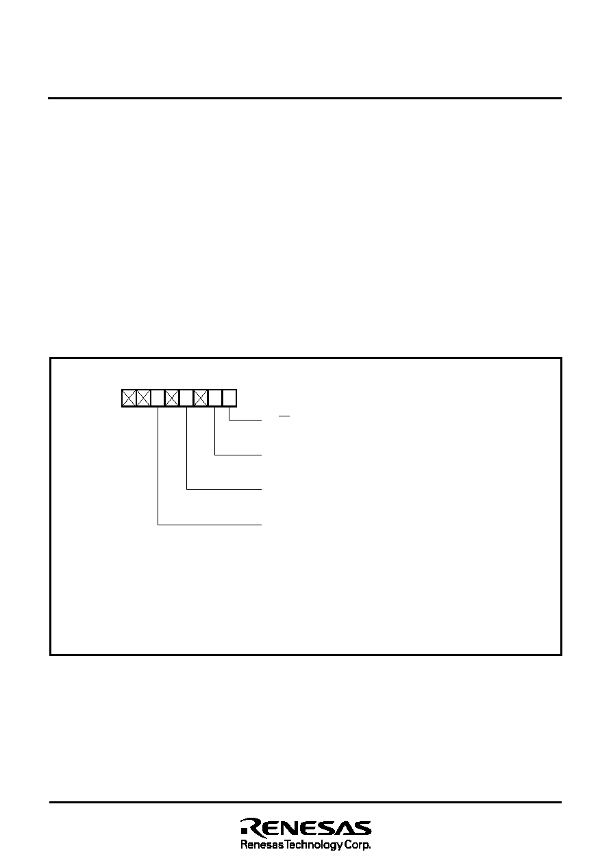
Fig. 7 Bit configuration of flash memory control register
Flash memory control register
RY/BY status bit
0: Busy (Programming or erasing is active.)
1: Ready
CPU reprogramming mode select bit (Note 2)
0: Normal mode (Software commands are ignored.)
1: CPU reprogramming mode (Software commands are acceptable.)
Flash memory reset bit (Note 3)
0: Normal operation
1: Reset
User ROM area select bit (Note 4)
(Valid only in the boot mode.)
0: Boot ROM area access
1: User ROM area access
Notes 1: The contents of the flash memory control register after reset is removed are “XX000001”.
2: To set “1”, writing of “0” to bit 1 and subsequent writing of “1” to bit 1 are necessary. Writing to bit 1 must be
performed by the user-original reprogramming control software in the internal RAM.
3: This bit is valid only when bit 1 = “1”. Before setting this bit to “0”, be sure to confirm that bit 0 = “1” after
setting this bit to “1” (reset). This bit 3 must be controlled with bit 1 = “1”.
4: Writing to bit 5 must be performed by the user-original reprogramming control software in the internal RAM.
765432
1
0
Address
9E16
相關(guān)PDF資料 |
PDF描述 |
|---|---|
| M37905M4C-XXXFP | 16-BIT, MROM, 20 MHz, MICROCONTROLLER, PQFP64 |
| M37905M4C-XXXFP | 16-BIT, MROM, 20 MHz, MICROCONTROLLER, PQFP64 |
| M37905M8C-XXXFP | 16-BIT, MROM, 20 MHz, MICROCONTROLLER, PQFP64 |
| M37905M8C-XXXSP | 16-BIT, MROM, 20 MHz, MICROCONTROLLER, PDIP64 |
| M37905M4C-XXXSP | 16-BIT, MROM, 20 MHz, MICROCONTROLLER, PDIP64 |
相關(guān)代理商/技術(shù)參數(shù) |
參數(shù)描述 |
|---|---|
| M37905M4C | 制造商:MITSUBISHI 制造商全稱:Mitsubishi Electric Semiconductor 功能描述:16 BIT CMOS MICROCOMPUTER |
| M37905M4C-XXXFP | 制造商:MITSUBISHI 制造商全稱:Mitsubishi Electric Semiconductor 功能描述:16 BIT CMOS MICROCOMPUTER |
| M37905M4C-XXXSP | 制造商:MITSUBISHI 制造商全稱:Mitsubishi Electric Semiconductor 功能描述:16 BIT CMOS MICROCOMPUTER |
| M37905M6C-XXXFP | 制造商:MITSUBISHI 制造商全稱:Mitsubishi Electric Semiconductor 功能描述:16 BIT CMOS MICROCOMPUTER |
| M37905M6C-XXXSP | 制造商:MITSUBISHI 制造商全稱:Mitsubishi Electric Semiconductor 功能描述:16 BIT CMOS MICROCOMPUTER |
發(fā)布緊急采購,3分鐘左右您將得到回復(fù)。