- 您現(xiàn)在的位置:買賣IC網(wǎng) > PDF目錄45029 > M37212EFSP 8-BIT, OTPROM, MICROCONTROLLER, PDIP52 PDF資料下載
參數(shù)資料
| 型號: | M37212EFSP |
| 元件分類: | 微控制器/微處理器 |
| 英文描述: | 8-BIT, OTPROM, MICROCONTROLLER, PDIP52 |
| 封裝: | 0.600 INCH, 1.78 MM PITCH, PLASTIC, SDIP-52 |
| 文件頁數(shù): | 64/119頁 |
| 文件大小: | 1308K |
| 代理商: | M37212EFSP |
第1頁第2頁第3頁第4頁第5頁第6頁第7頁第8頁第9頁第10頁第11頁第12頁第13頁第14頁第15頁第16頁第17頁第18頁第19頁第20頁第21頁第22頁第23頁第24頁第25頁第26頁第27頁第28頁第29頁第30頁第31頁第32頁第33頁第34頁第35頁第36頁第37頁第38頁第39頁第40頁第41頁第42頁第43頁第44頁第45頁第46頁第47頁第48頁第49頁第50頁第51頁第52頁第53頁第54頁第55頁第56頁第57頁第58頁第59頁第60頁第61頁第62頁第63頁當前第64頁第65頁第66頁第67頁第68頁第69頁第70頁第71頁第72頁第73頁第74頁第75頁第76頁第77頁第78頁第79頁第80頁第81頁第82頁第83頁第84頁第85頁第86頁第87頁第88頁第89頁第90頁第91頁第92頁第93頁第94頁第95頁第96頁第97頁第98頁第99頁第100頁第101頁第102頁第103頁第104頁第105頁第106頁第107頁第108頁第109頁第110頁第111頁第112頁第113頁第114頁第115頁第116頁第117頁第118頁第119頁
49
SINGLE-CHIP 8-BIT CMOS MICROCOMPUTER for VOLTAGE SYNTHESIZER
with ON-SCREEN DISPLAY CONTROLLER
M37212M4/M8–XXXSP, M37212M6–XXXSP/FP
M37212EFSP/FP
MITSUBISHI MICROCOMPUTERS
Rev. 1.0
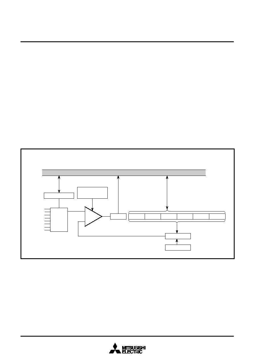
8.8 A-D COMPARATOR
A-D comparator consists of 6-bit D-A converter and comparator. A-D
comparator block diagram is shown in Figure 8.8.1.
The reference voltage “Vref” for D-A conversion is set by bits 0 to 5 of
the A-D control register (address 00EF16).
The comparison result of the analog input voltage and the reference
voltage “Vref” is stored in bit 4 of the A-D mode register (address
00EE16).
For A-D comparison, set “0” to corresponding bits of the direction
register to use ports as analog input pins. Write the data for select of
analog input pins to bits 0 to 2 of the A-D control register 1 and write
the digital value corresponding to Vref to be compared to the bits 0
to 5 of the A-D control register. The voltage comparison starts by
writing to the A-D control register 2, and it is completed after 16 ma-
chine cycles (NOP instruction ! 8).
Fig. 8.8.1 A-D Comparator Block Diagram
A-D mode register
Bits 0 to 2
Comparator control
Data bus
Bit 4
Switch tree
A-D control
register
Resistor ladder
Compa-
rator
Analog
signal
switch
Bit 5Bit 4Bit 3Bit 2Bit 1
Bit 0
A-D mode
register
A-D1
A-D2
A-D3
A-D4
A-D5
A-D6
A-D7
A-D8
相關PDF資料 |
PDF描述 |
|---|---|
| M37221EF-XXXSP | 8-BIT, OTPROM, 8 MHz, MICROCONTROLLER, PDIP42 |
| M37221EFSP | 8-BIT, OTPROM, 8 MHz, MICROCONTROLLER, PDIP42 |
| M37221M6-XXXFP | 8-BIT, MROM, 8.1 MHz, MICROCONTROLLER, PDSO42 |
| M37221M6-XXXSP | 8-BIT, MROM, 8.1 MHz, MICROCONTROLLER, PDIP42 |
| M37221M6H-XXXFP | 8-BIT, MROM, 8.1 MHz, MICROCONTROLLER, PDSO42 |
相關代理商/技術參數(shù) |
參數(shù)描述 |
|---|---|
| M37212EFSP/FP | 制造商:MITSUBISHI 制造商全稱:Mitsubishi Electric Semiconductor 功能描述:SINGLE-CHIP 8-BIT CMOS MICROCOMPUTER for VOLTAGE SYNTHESIZER |
| M37212M4 | 制造商:RENESAS 制造商全稱:Renesas Technology Corp 功能描述:SINGLE-CHIP 8-BIT CMOS MICROCOMPUTER for VOLTAGE SYNTHESIZER with ON-SCREEN DISPLAY CONTROLLER |
| M37212M4-054SP | 制造商:MITSUBISHI 制造商全稱:Mitsubishi Electric Semiconductor 功能描述:SINGLE-CHIP 8-BIT CMOS MICROCOMPUTER for VOLTAGE SYNTHESIZER with ON-SCREEN DISPLAY CONTROLLER |
| M37212M4-XXXSP | 制造商:RENESAS 制造商全稱:Renesas Technology Corp 功能描述:SINGLE-CHIP 8-BIT CMOS MICROCOMPUTER for VOLTAGE SYNTHESIZER with ON-SCREEN DISPLAY CONTROLLER |
| M37212M6-XXXFP | 制造商:RENESAS 制造商全稱:Renesas Technology Corp 功能描述:SINGLE-CHIP 8-BIT CMOS MICROCOMPUTER for VOLTAGE SYNTHESIZER with ON-SCREEN DISPLAY CONTROLLER |
發(fā)布緊急采購,3分鐘左右您將得到回復。