- 您現(xiàn)在的位置:買賣IC網(wǎng) > PDF目錄359054 > M34C00 (意法半導(dǎo)體) SWITCH TACT 6MM SQ L=5.85MM160GF PDF資料下載
參數(shù)資料
| 型號: | M34C00 |
| 廠商: | 意法半導(dǎo)體 |
| 英文描述: | SWITCH TACT 6MM SQ L=5.85MM160GF |
| 中文描述: | 3 × 128位串行IC總線的EEPROM為電子工程,標簽 |
| 文件頁數(shù): | 3/15頁 |
| 文件大?。?/td> | 114K |
| 代理商: | M34C00 |

3/15
M34C00
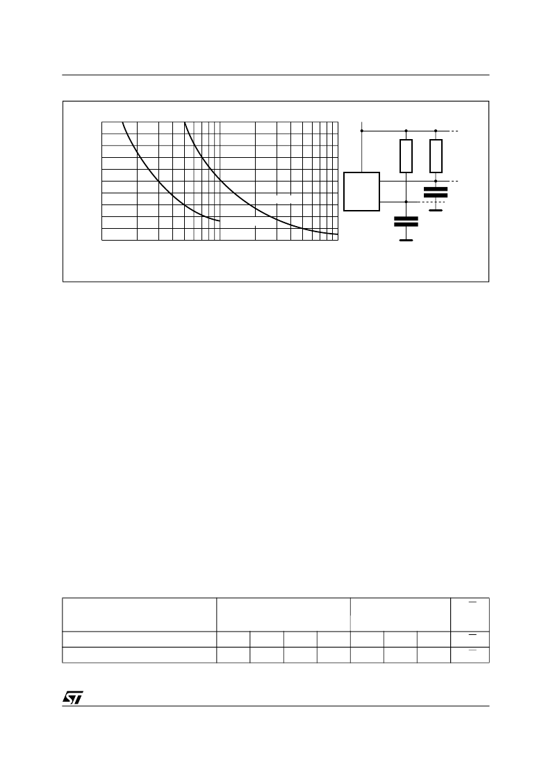
Figure 3. Maximum R
L
Value versus Bus Capacitance (C
BUS
) for an I
2
C Bus
AI01665
VCC
CBUS
SDA
RL
MASTER
RL
SCL
CBUS
100
0
4
8
12
16
20
CBUS (pF)
M
)
10
1000
fc = 400kHz
fc = 100kHz
Table 3. Device Select Code
Note: 1. The most significant bit (b7) is sent first.
Device Type Identifier
1
RW
b7
b6
b5
b4
b3
b2
b1
b0
Memory Area Select Code (three arrays)
1
0
1
0
1
1
1
RW
Protection Register Select Code
0
1
1
0
1
1
1
RW
collector signals on the bus. A pull up resistor must
be connected from Serial Data (SDA) to V
CC
.
(Figure 3 indicates how the value of the pull-up
resistor can be calculated).
DEVICE OPERATION
The device supports the I
2
C protocol. This is
summarized in Figure 4. Any device that sends
data on to the bus is defined to be a transmitter,
and any device that reads the data to be a
receiver. The device that controls the data transfer
is known as the bus master, and the other as the
slave device. A data transfer can only be initiated
by the bus master, which will also provide the
serial clock for synchronization. The M34C00
device is always a slave in all communication.
Start Condition
Start is identified by a falling edge of Serial Data
(SDA) while Serial Clock (SCL) is stable in the
High state. A Start condition must precede any
data transfer command. The device continuously
monitors (except during a programming cycle)
Serial Data (SDA) and Serial Clock (SCL) for a
Start condition, and will not respond unless one is
given.
Stop Condition
Stop is identified by a rising edge of Serial Data
(SDA) while Serial Clock (SCL) is stable, and
driven High. A Stop condition terminates
communication between the device and the bus
master. A Read command that is followed by
NoAck can be followed by a Stop condition to force
the device into the Stand-by mode. A Stop
condition at the end of a Write command triggers
the internal EEPROM Write cycle.
Acknowledge Bit (ACK)
The acknowledge bit is used to indicate a
successful byte transfer. The bus transmitter,
whether it be bus master or slave device, releases
Serial Data (SDA) after sending eight bits of data.
During the 9
th
clock pulse period, the receiver pulls
Serial Data (SDA) Low to acknowledge the receipt
of the eight data bits.
Data Input
During data input, the device samples Serial Data
(SDA) on the rising edge of Serial Clock (SCL).
For correct device operation, Serial Data (SDA)
must be stable during the rising edge of Serial
Clock (SCL), and the data on Serial Data (SDA)
相關(guān)PDF資料 |
PDF描述 |
|---|---|
| M34C00-WDW6T | 3 x 128 bit Serial IC Bus EEPROM For ee-Tags |
| M34C00-WMN6T | 3 x 128 bit Serial IC Bus EEPROM For ee-Tags |
| M34C00MN | 3 x 128 bit Serial IC Bus EEPROM For ee-Tags |
| M34C00DW | 3 x 128 bit Serial IC Bus EEPROM For ee-Tags |
| M34C02 | 2 Kbit Serial IC Bus EEPROM For DIMM Serial Presence Detect |
相關(guān)代理商/技術(shù)參數(shù) |
參數(shù)描述 |
|---|---|
| M34C00DW | 制造商:STMICROELECTRONICS 制造商全稱:STMicroelectronics 功能描述:3 x 128 bit Serial IC Bus EEPROM For ee-Tags |
| M34C00MN | 制造商:STMICROELECTRONICS 制造商全稱:STMicroelectronics 功能描述:3 x 128 bit Serial IC Bus EEPROM For ee-Tags |
| M34C00-WDW6T | 制造商:STMICROELECTRONICS 制造商全稱:STMicroelectronics 功能描述:3 x 128 bit Serial IC Bus EEPROM For ee-Tags |
| M34C00-WMN6 | 制造商:STMicroelectronics 功能描述: |
| M34C00-WMN6T | 制造商:STMICROELECTRONICS 制造商全稱:STMicroelectronics 功能描述:3 x 128 bit Serial IC Bus EEPROM For ee-Tags |
發(fā)布緊急采購,3分鐘左右您將得到回復(fù)。