- 您現(xiàn)在的位置:買賣IC網(wǎng) > PDF目錄370837 > M34250M2-086FP (Mitsubishi Electric Corporation) SINGLE-CHIP 4-BIT CMOS MICROCOMPUTER PDF資料下載
參數(shù)資料
| 型號(hào): | M34250M2-086FP |
| 廠商: | Mitsubishi Electric Corporation |
| 英文描述: | SINGLE-CHIP 4-BIT CMOS MICROCOMPUTER |
| 中文描述: | 單芯片4位微機(jī)的CMOS |
| 文件頁數(shù): | 50/58頁 |
| 文件大?。?/td> | 331K |
| 代理商: | M34250M2-086FP |
第1頁第2頁第3頁第4頁第5頁第6頁第7頁第8頁第9頁第10頁第11頁第12頁第13頁第14頁第15頁第16頁第17頁第18頁第19頁第20頁第21頁第22頁第23頁第24頁第25頁第26頁第27頁第28頁第29頁第30頁第31頁第32頁第33頁第34頁第35頁第36頁第37頁第38頁第39頁第40頁第41頁第42頁第43頁第44頁第45頁第46頁第47頁第48頁第49頁當(dāng)前第50頁第51頁第52頁第53頁第54頁第55頁第56頁第57頁第58頁

MITSUBISHI
ELECTRIC
50
MITSUBISHI MICROCOMPUTERS
4250 Group
SINGLE-CHIP 4-BIT CMOS MICROCOMPUTER
Notes 1: “R” represents read enabled, and “W” represents write enabled.
2: Set a value to the bit 2 of register K0, and execute the SNZ0 instruction to clear the EXF0 flag to “0” after executing at least
one instruction. According to the input state of G
0
/INT pin, the external interrupt request flag (EXF0) may be set to “1” when
the interrupt valid waveform is changed.
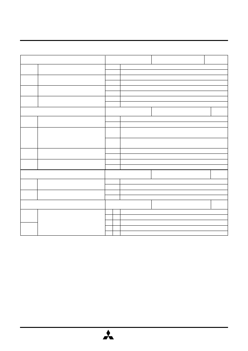
CONTROL REGISTERS
PU0
1
PU0
0
Pull-up transistor OFF
Pull-up transistor ON
Pull-up transistor OFF
Pull-up transistor ON
Ports C and K
pull-up transistor control bit
Ports G
0
–G
3
pull-up transistor control bit
Pull-up control register PU0
at reset : 00
2
at RAM back-up : state retained
0
1
0
1
W
V1
3
V1
2
V1
1
V1
0
Port G
1
(I/O)
T
OUT
pin (output) / port G
1
(input)
Prescaler stop (initial state) / timer 1 stop (state retained)
Prescaler/timer 1 operation
Interrupt disabled (SNZ1 instruction is valid)
Interrupt enabled (SNZ1 instruction is invalid)
Interrupt disabled (SNZ0 instruction is valid)
Interrupt enabled (SNZ0 instruction is invalid)
0
1
0
1
0
1
0
1
G
1
/T
OUT
pin function selection bit
Prescaler/timer 1 operation start bit
Timer 1 interrupt enable bit
External interrupt enable bit
Timer control register V1
R/W
at reset : 0000
2
at RAM back-up : 0000
2
K0
3
K0
2
K0
1
K0
0
Instruction clock divided by 4
Instruction clock divided by 512
Rising waveform (“L”
→
“H”)
Falling waveform (“H”
→
“L”)
Key-on wakeup not used
Key-on wakeup used (“L” level recognized)
Key-on wakeup not used
Key-on wakeup used (“L” level recognized)
Prescaler dividing ratio selection bit
Interrupt valid waveform for INT pin/
key-on wakeup valid waveform selection
bit (Note 2)
Ports G
1
–G
3
key-on wakeup control bit
Ports S
0
–S
3
key-on wakeup control bit
Key-on wakeup control register K0
at reset : 0000
2
at RAM back-up : state retained
0
1
0
1
0
1
0
1
R/W
Functions
XOR operation
OR operation
AND operation
Not available
Logic operation function selection bits
Logic operation selection register LO
at reset : 00
2
at RAM back-up : 00
2
LO
1
0
0
1
1
W
LO
0
0
1
0
1
LO
1
LO
0
相關(guān)PDF資料 |
PDF描述 |
|---|---|
| M34250M2-099FP | SINGLE-CHIP 4-BIT CMOS MICROCOMPUTER |
| M34250M2-116FP | SINGLE-CHIP 4-BIT CMOS MICROCOMPUTER |
| M34250 | Single Chip 4 Bits CMOS Microcomputer(4位單片機(jī)) |
| M34250E2FP | SINGLE-CHIP 4-BIT CMOS MICROCOMPUTER |
| M34250M2 | SINGLE-CHIP 4-BIT CMOS MICROCOMPUTER |
相關(guān)代理商/技術(shù)參數(shù) |
參數(shù)描述 |
|---|---|
| M34250M2-099FP | 制造商:MITSUBISHI 制造商全稱:Mitsubishi Electric Semiconductor 功能描述:SINGLE-CHIP 4-BIT CMOS MICROCOMPUTER |
| M34250M2-116FP | 制造商:MITSUBISHI 制造商全稱:Mitsubishi Electric Semiconductor 功能描述:SINGLE-CHIP 4-BIT CMOS MICROCOMPUTER |
| M34250M2-XXXFP | 制造商:RENESAS 制造商全稱:Renesas Technology Corp 功能描述:SINGLE-CHIP 4-BIT CMOS MICROCOMPUTER |
| M3426 SL002 | 制造商:Alpha Wire 功能描述:CBL 8PR 24AWG SLT 500' |
| M3426 SL005 | 制造商:Alpha Wire 功能描述:CBL 8PR 24AWG SLT 100' |
發(fā)布緊急采購,3分鐘左右您將得到回復(fù)。