- 您現(xiàn)在的位置:買賣IC網 > PDF目錄377822 > M34116 (意法半導體) PCM CONFERENCE CALL AND TONE GENERATION CIRCUIT PDF資料下載
參數(shù)資料
| 型號: | M34116 |
| 廠商: | 意法半導體 |
| 英文描述: | PCM CONFERENCE CALL AND TONE GENERATION CIRCUIT |
| 中文描述: | 的PCM電話會議和音產生電路 |
| 文件頁數(shù): | 14/23頁 |
| 文件大小: | 374K |
| 代理商: | M34116 |
M116 INSTRUCTION SET
(continued)
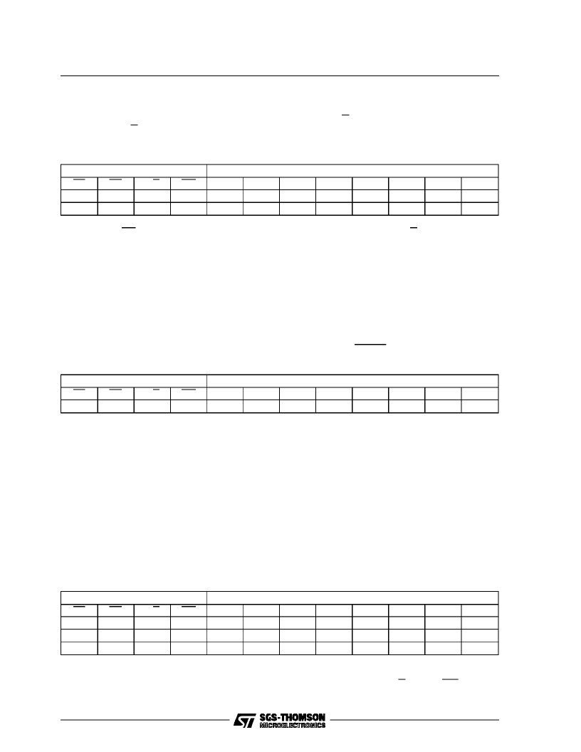
INSTRUCTION 4: OVERFLOWINFORMATION
Two bytes are neededto know the status of all 10 conferences:C/D = 0 reads the first byte (first 8 con-
ferences) and C/D = 1 reads the second byte (the last 2 conferences).A conferenceis in overflow when
the correspondingbit is high.
Instruction 4 Format
Control Signal
RD
0
0
Data Bus
D4
CF5
X
CS
0
0
C/D
0
1
WR
1
1
D7
CF8
X
D6
CF7
X
D5
CF6
X
D3
CF4
X
D2
CF3
X
D1
CF2
CF10
D0
CF1
CF9
CF10 – CF1: Conference in overflowwhen high.
nb: as long as RD remains low, the overflow status of the conferenceselectedby C/D can be monitored
in realtime.
INSTRUCTION 5: OPERATINGMODE
The single byte needed contains the Extra bit (D6), the format bits F1–F0 (D5–D4) and the opcode
(0101).
The E bit must be E = 1 when the PCM frame contains a number of bit multiple of eight plus on bit (ex.
PCM frame at 1544Kbit/s). Normally E = 0. The bits F1–F0 select the kinds of PCM format byte accord-
ing table 1. After Reset the default values corresponds to F1 = 0, F0 = 1 if A–law is selectedand F1 = 1,
F0 = 1 if Mu–law is selected. All channels must be disconnectedwhen the OperatingMode Instructionis
sent. They must remaindisconnectedfor at least two time framesafter the instruction was sent.
We recommende to use this instruction right after the RESET (see pin RESET decription).
Instruction 5 Format
Control Signal
RD
1
Data Bus
D4
F0
CS
0
C/D
1
WR
0
D7
X
D6
E
D5
F1
D3
0
D2
1
D1
0
D0
1
E: Extra bit insertion (active when E = 1)
F1 – F0: PCM byte Format selection(see also table 1)
00 = no bit inverted
01 = evenbit (B0–B2–B4–B6)inverted
10 = odd bit (B1–B3–B5)inverted
11 = all bit (B0–B1–B2–B3–B4–B5–B6)inverted
INSTRUCTION 6: STATUS
Three bytes areneeded:
1) The first byte containsthe numberof the channel;
2) The second byte contains the opcode (0110);
3) By a reding cycle you extract from the third byte the information about the operating mode of the
channel (no connection or transparentmode or number of the conference,bits D4–D7); the attenuation
(D2–D3) and noise suppressionvalues(D0–D1) eventuallyinserted.
This readingcycle must be executedat least one frame after the end of the opcodewriting cycle.
Instruction 6 Format
Control Signal
RD
1
1
0
Data Bus
D4
C4
X
P0
CS
0
0
0
C/D
0
1
1
WR
0
0
1
D7
X
X
P3
D6
X
X
P2
D5
X
X
P1
D3
C3
0
A1
D2
C2
1
A0
D1
C1
1
T1
D0
C0
0
T0
P3–P0: channelmode operation information
0000 = no connection
1111 = transparentmode
1010 – 0001 = conference mode
P3–P0give the number of the conferenc
nb: the instruction 6 enables the dat bus to read
the status until reset by C/D = 0 and WR = 1.
M34116
14/23
相關PDF資料 |
PDF描述 |
|---|---|
| M34116B1 | PCM CONFERENCE CALL AND TONE GENERATION CIRCUIT |
| M34116C1 | PCM CONFERENCE CALL AND TONE GENERATION CIRCUIT |
| M34C02-RDW6G | 2 Kbit Serial IC Bus EEPROM for DIMM serial presence detect |
| M34C02-RDW6P | 2 Kbit Serial IC Bus EEPROM for DIMM serial presence detect |
| M34C02-RDW6TG | 2 Kbit Serial IC Bus EEPROM for DIMM serial presence detect |
相關代理商/技術參數(shù) |
參數(shù)描述 |
|---|---|
| M34116B1 | 功能描述:IC PCM TONE CIRCUIT 24-DIP RoHS:否 類別:集成電路 (IC) >> 接口 - 電信 系列:- 產品培訓模塊:Lead (SnPb) Finish for COTS 產品變化通告:Product Discontinuation 06/Feb/2012 標準包裝:750 系列:* |
| M34116C1 | 制造商:STMICROELECTRONICS 制造商全稱:STMicroelectronics 功能描述:PCM CONFERENCE CALL AND TONE GENERATION CIRCUIT |
| M3412 | 制造商:Tamura Corporation of America 功能描述: |
| M3414HVSD/NOPB | 制造商:Texas Instruments 功能描述: |
| M34166TVG | 制造商:ON Semiconductor 功能描述: |
發(fā)布緊急采購,3分鐘左右您將得到回復。