- 您現(xiàn)在的位置:買(mǎi)賣(mài)IC網(wǎng) > PDF目錄377800 > M-991-01SMTR (CLARE INC) Call Progress Tone Generator PDF資料下載
參數(shù)資料
| 型號(hào): | M-991-01SMTR |
| 廠商: | CLARE INC |
| 元件分類(lèi): | 無(wú)繩電話/電話 |
| 英文描述: | Call Progress Tone Generator |
| 中文描述: | CALL PROGRESS TONE GENERATOR, PDSO16 |
| 封裝: | SOIC-16 |
| 文件頁(yè)數(shù): | 2/6頁(yè) |
| 文件大?。?/td> | 171K |
| 代理商: | M-991-01SMTR |
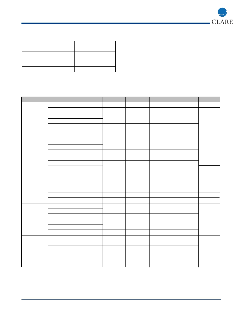
Absolute Maximum Ratings
Storage Temperature
Operating Ambient Temperature
Operating Ambient Temperature
for the M-991-02SM
V
DD
Any Input Voltage
Note:
1. Exceeding these ratings may permanently damage the M-991.
-55° to 125° C
-25° to 70° C
-40° to 85° C
7.0V
V
SS
-0.6 to V
DD
+0.6V
www.clare.com
2
M-991
Rev. 1
7. At XOUT pin as compared to 3.579545 MHz.
8. OUTDRIVE with load >5 KW/OUTDRIVE with
540 W load.
9. Resistance at V
to V
DD
or V
SS
> 1 MW.
10. Crystal oscillator active.
11. Measured 90% to 10%.
Absolute Maximum Ratings are stress ratings. Stresses in
excess of these ratings can cause permanent damage to
the device. Functional operation of the device at these or
any other conditions beyond those indicated in the opera-
tional sections of this data sheet is not implied. Exposure of
the device to the absolute maximum ratings for an extend-
ed period may degrade the device and effect its reliability.
Specifications
Parameter
Min
4.75
-
Typ
-
2.0/4.0
Max
5.25
-
Units
V
mA
Notes
1
8
Power Supply
and Reference
V
DD
Current Drain, IDD
V
REF
Pin:
Deviation from (V
DD
+ V
SS
)/2
Internal Resistance from V
REF
to V
DD
, V
SS
Frequency Deviation
External Clock: (XOUT open)
V
IL
V
IH
Duty Cycle
XIN, XOUT Loading:
Capacitance
Resistance
Frequency Deviation
Level
Distorting Components
Idle
OUTDRIVE Envelope Rise Time
DX, CE Pns:
V
IL
V
IH
Mute Pins:
VOL (I
SINK
= -100 μA)
V
OH
(I
SOURCE
= 100 μA)
Data Setup (t
DS
)
Data Hold (t
DH
)
Chip Enable Fall (t
PL
)
Tone On Delay (t
TO
)
Tone Off Delay (t
TD
)
MuteDelayfromOutdrive(t
MO
)
-2
-
-
+2
6.75
%
k
3.25
Oscillator
-0.01
-
+0.01
%
7
0
-
-
-
0.2
V
DD
60
V
V
%
V
DD
- 0.2
40
-
-
-
-
-
-
-
-
10
-
+0.5
180
-
-60
4
pF
M
%
mV
dB
dBm
ms
10
-
-
2
3
4
5
20
-0.5
100
-35
-
-
Tone Output
Control
-
-
-
0.5
-
V
V
6
2.5
-
-
-
-
-
-
-
-
-
1.5
-
-
-
90
5
5
200
V
V
ns
ns
ns
ms
ms
ns
V
DD
- 1.5
200
10
-
-
-
-
Timing
11
Notes:
(unless otherwise specified)
1. All DC voltages are referenced to V
SS
.
2. Vrms per tone, 540 W load.
3. Any one frequency relative to the lowest level output tone (f<4000 Hz).
4. 0 dBm = 0.775 Vrms.
5. To 90% maximum amplitude.
6. For all supply voltages in the operating range.
相關(guān)PDF資料 |
PDF描述 |
|---|---|
| M-991-02SM | Call Progress Tone Generator |
| M-991-02SMTR | CA-BAYONET |
| M-991 | Call Progress Tone Generator |
| M1025-1026 | Low-Cost PC Hardware Monitor ASIC |
| M12L128168A_06 | 2M x 16 Bit x 4 Banks Synchronous DRAM |
相關(guān)代理商/技術(shù)參數(shù) |
參數(shù)描述 |
|---|---|
| M-991-02SM | 制造商:CLARE 制造商全稱(chēng):Clare, Inc. 功能描述:Call Progress Tone Generator |
| M-991-02SMTR | 制造商:CLARE 制造商全稱(chēng):Clare, Inc. 功能描述:Call Progress Tone Generator |
| M9911 | 制造商:Tamura Corporation of America 功能描述: |
| M9913 | 制造商:Tamura Corporation of America 功能描述: |
| M9914EIN WAF | 制造商:Texas Instruments 功能描述: |
發(fā)布緊急采購(gòu),3分鐘左右您將得到回復(fù)。