- 您現(xiàn)在的位置:買賣IC網(wǎng) > PDF目錄369882 > LX8817-25CDF Low Drop Out Regulator - Dual PDF資料下載
參數(shù)資料
| 型號: | LX8817-25CDF |
| 英文描述: | Low Drop Out Regulator - Dual |
| 中文描述: | 低壓差穩(wěn)壓器-雙 |
| 文件頁數(shù): | 3/8頁 |
| 文件大小: | 217K |
| 代理商: | LX8817-25CDF |

Microsemi
Linfinity Microelectronics Division
11861 Western Avenue, Garden Grove, CA. 92841, 714-898-8121, Fax: 714-893-2570
Page 3
Copyright
2000
Rev. 0.3D, 2002-01-08
W
M
.
C
LX8817
Dual Channel 2.5A Low Dropout Regulator
P
RODUCTION
D
ATA
S
HEET
L I N F I N I T Y D I V I S I O N
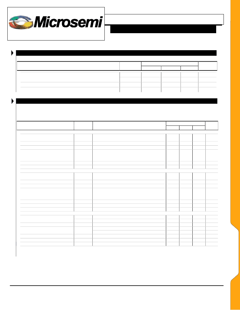
R E C O M M E N D E D M A X O P E R A T I N G C O N D I T I O N
LX8817-25
Typ
Parameter
Symbol
Min
Max
Units
V
CTRL
V
PWR
I
1,
I
2
T
J
10
7.5
3.0
125
V
V
A
°
C
Input Voltage
Load Current (Internally Limited)
Operating Junction Temperature
E L E C T R I C A L C H A R A C T E R I S T I C S
Unless otherwise specified, the following specifications apply over the operating ambient temperature 0
°
C
≤
T
A
≤
125
°
C except where
otherwise noted and the following test conditions: V
CTRL
= 5V, V
PWR
= 3.3V I
OUT
= 5mA, C
1, 2, 3, 4
= 10
μ
F (Tantalum), and T
J
= T
A
using
low duty cycling methods.
LX8817-25
Typ
Parameter
Symbol
Test Conditions
Min
Max
Units
!
FIXED OUTPUT
Output Voltage
LX8817-2500
Line Regulation
Load Regulation
V
1
5mA < I
1
< 2.5A, 3.75V < V
CTRL
< 10V
3.3V < V
PWR
< 5.5V
3.3V<V
CTRL
<10V, 3.3V<V
PWR
<5.5V, I
1
= 5mA
5mA < I
1
< 2.5A, V
CTRL
=5V, V
PWR
=3.3V
I
1
= 2.5A,
V
1
= -2%
I
1
= 2.0A,
V
1
= -2%
I
1
= 1.0A,
V
1
= -2%
Note 1
2.438
2.500
2.538
V
V
1
(V
IN
)
V
1
(I
1
)
1
1
5
5
mV
mV
Dropout Voltage (PWR)
V
PWR
-V
1
0.500
0.375
0.225
3.0
0
0.730
0.580
0.390
5
V
Current Limit
Minimum Load Current
!
ADJUSTABLE OUTPUT
I
1 (MAX)
I
1
2.55
A
mA
Reference Voltage
V
2
5mA < I
2
< 2.5A, 3.75V < V
CTRL
< 10V
3.3V < V
PWR
< 5.5V
3.3V<V
CTRL
<10V, 3.3V<V
PWR
<5.5V, I
2
= 5mA
5mA < I
2
< 2.5A, V
CTRL
=5V, V
PWR
=3.3V
I
2
= 2.5A,
V
2
= -2%
I
2
= 2.0A,
V
2
= -2%
I
2
= 1.0A,
V
2
= -2%
Note 1
V
PWR
Rising, 3.0V<V
CTRL
< 10V, Both Outputs Off
I
1
=I
2
=5mA
I
1
=I
2
=2.5A
f=120Hz, T
J
= 25
°
C
10Hz < f < 10kHz
1.231
1.250
1.288
V
Line Regulation
Load Regulation
V
2
(V
IN
)
V
2
(I
2
)
0.05
10
0.500
0.375
0.225
3.0
1
1
3
6
75
0.003
160
3
19
0.730
0.580
0.390
5
2
2.6
3.3
2.2
5
10
mV
mV
Dropout Voltage
V
PWR
-V
2
V
Current Limit
Minimum Load Current
Adjust Pin Bias Current
!
ENTIRE REGULATOR
Under Voltage Lockout
Ripple Rejection
RMS Output Noise
Thermal Shutdown
Note 1: Minimum load current is defined as the amount of output current required to maintain regulation. Typically this current provides the bias to the external resistor divider
network used to set the output voltage.
I
2 (MAX)
I
2
I
ADJ
2.55
60
A
mA
μ
A
V
V
V
mA
mA
dB
%V
OUT
°
C
V
PWR
V
CONTROL
Minimum Operating Voltage
Quiescent Current
I
Q
PSRR
T
JSD
E
L
E
C
T
R
I
C
A
L
S
相關(guān)PDF資料 |
PDF描述 |
|---|---|
| LX8817-25CDFT | Analog IC |
| LX8818-01CDT | Low Drop Out Regulator - Positive Adjustable |
| LX8818-02CLM | Low Drop Out Regulator - Positive Adjustable |
| LX9508 | Backlight Cable Assembly |
| LXD970A | LXD970A - LXD970A Demo Board for 10/100 and 100BASE-FX Applications |
相關(guān)代理商/技術(shù)參數(shù) |
參數(shù)描述 |
|---|---|
| LX8817-25CDFT | 制造商:Microsemi Corporation 功能描述:LX8817-25CDFT - Bulk |
| LX8818-01CDT | 制造商:未知廠家 制造商全稱:未知廠家 功能描述:Low Drop Out Regulator - Positive Adjustable |
| LX8818-02CLM | 制造商:未知廠家 制造商全稱:未知廠家 功能描述:Low Drop Out Regulator - Positive Adjustable |
| LX8819 | 制造商:MICROSEMI 制造商全稱:Microsemi Corporation 功能描述:Dual Channel 1A Low Dropout Regulator |
| LX8819-25CDF | 制造商:MICROSEMI 制造商全稱:Microsemi Corporation 功能描述:Dual Channel 1A Low Dropout Regulator |
發(fā)布緊急采購,3分鐘左右您將得到回復(fù)。