- 您現(xiàn)在的位置:買(mǎi)賣IC網(wǎng) > PDF目錄45005 > LWR1801-6ERFK2G (POWER-ONE INC) DC-DC REG PWR SUPPLY MODULE PDF資料下載
參數(shù)資料
| 型號(hào): | LWR1801-6ERFK2G |
| 廠商: | POWER-ONE INC |
| 元件分類: | 電源模塊 |
| 英文描述: | DC-DC REG PWR SUPPLY MODULE |
| 封裝: | ROHS COMPLIANT |
| 文件頁(yè)數(shù): | 23/28頁(yè) |
| 文件大小: | 1316K |
| 代理商: | LWR1801-6ERFK2G |
第1頁(yè)第2頁(yè)第3頁(yè)第4頁(yè)第5頁(yè)第6頁(yè)第7頁(yè)第8頁(yè)第9頁(yè)第10頁(yè)第11頁(yè)第12頁(yè)第13頁(yè)第14頁(yè)第15頁(yè)第16頁(yè)第17頁(yè)第18頁(yè)第19頁(yè)第20頁(yè)第21頁(yè)第22頁(yè)當(dāng)前第23頁(yè)第24頁(yè)第25頁(yè)第26頁(yè)第27頁(yè)第28頁(yè)

BCD20020-G REV AA
Page 4 of 28
www.power-one.com
W Series Data Sheet
125, 250 Watt AC-DC and DC-DC DIN-Rail Converters
Input
filter
Input
filter
V
o/Io control
Output
filter
2nd control loop (SELV)
Control circuit
including
PFC and
input OVP/UVP
L
N
Vo+
Vo–
C
y
C
y
C
y
C
Y
C
Y
AUX
Fuse
2nd fuse
(option F)
2
1
03103a
Shunt
3
4
5
8
9
2
3
6
7
1
11
10
Vo–
Vo+
Rectifier
+
Functional Description
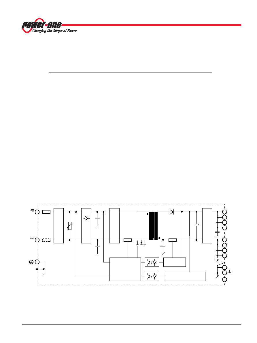
The W Series converters are primary controlled AC-DC or DC-
DC flyback converters with a constant switching frequency of
130 kHz. The power-factor-corrected single-step conversion of
the input voltage to a low output voltage results in extremely
high efficiency. Depending upon the output power, the
converters are fitted with one (125 W) or two (250 W)
powertrains. Models with two powertrains have one or two
outputs. Double-output models exhibit indiviually regulated
powertrains.
The input voltage is fed via fuse, filter, and rectifier to the main
transformer, designed in planar technique. The input filter with
very small input capacitance generates virtually no inrush
current. An input transient suppressor protects the converter
against high voltage peaks and surges. Input over- and
undervoltage lockout as well as input current limitation protect
the converter from operation outside of its specification. The
input voltage waveform is sensed by the primary control logic
to allow active power factor correction, forcing the input current
to follow the input voltage waveform.
The secondary side of the main transformer supplies via the
rectifier diode a large electrolytic output storage capacitor
providing for the hold-up time. Double-output models exhibit
an individual control logic each. The output voltage and the
output current are measured and fed back to the primary
control logic via an optocoupler. A second control loop
monitors the output voltage. It disables the output in the case
of a failure in the control logic and limits the output voltage.
Built-in temperature sensors monitor the internal temperature
of each powertrain. If the temperature exceeds the limit, the
converter reduces the output power continuously to keep the
temperature below its limit. A green LED on the front cover
confirms the presence of the output voltage(s).
The R input (option R, M1, or M2) allows for external
adjustment of the output voltage by means of a resistor or an
external voltage source. An external sensor can be connected
to the R input and allows for temperature-controlled battery
charging (see Accessories).
Fig. 1
LWR 125 W and LWN 250 W single-output converters.
EWR and EWN models have a link (standard) or a decoupling diode (option Q)
rather than a bridge rectifier in the positive input line.
Product Marking
Basic type designation, applicable safety approval and
recognition marks, CE mark, warnings, pin designation,
Power-One company logo.
Specific type designation, input voltage range, nominal output
voltages and currents, degree of protection, batch no., serial
no., and data code including production site, version, and date
of production.
相關(guān)PDF資料 |
PDF描述 |
|---|---|
| LWN2660-6ED5FK2G | DC-DC REG PWR SUPPLY MODULE |
| LWN2660-6EM2FK2G | DC-DC REG PWR SUPPLY MODULE |
| LWN1601-6ERFK2G | DC-DC REG PWR SUPPLY MODULE |
| LWN2770-6ED5FK2G | DC-DC REG PWR SUPPLY MODULE |
| LWR1701-6EM2FK2G | DC-DC REG PWR SUPPLY MODULE |
相關(guān)代理商/技術(shù)參數(shù) |
參數(shù)描述 |
|---|---|
| LWR3006A18C300 | 制造商:Molex 功能描述: |
| LWR3A00A18C300 | 制造商:Molex 功能描述: |
| LWR4000A18C300 | 制造商:Molex 功能描述: |
| LWR5A06A18C300 | 制造商:Molex 功能描述: |
| LWRA 220A | 制造商:Schneider Electric 功能描述:PHASE CTRL RLY, 11-PIN, 3x220VAC |
發(fā)布緊急采購(gòu),3分鐘左右您將得到回復(fù)。