- 您現(xiàn)在的位置:買賣IC網(wǎng) > PDF目錄39438 > LW15-11 (POWER-ONE INC) 3-OUTPUT 17.5 W AC-DC REG PWR SUPPLY MODULE PDF資料下載
參數(shù)資料
| 型號: | LW15-11 |
| 廠商: | POWER-ONE INC |
| 元件分類: | 電源模塊 |
| 英文描述: | 3-OUTPUT 17.5 W AC-DC REG PWR SUPPLY MODULE |
| 文件頁數(shù): | 5/9頁 |
| 文件大小: | 373K |
| 代理商: | LW15-11 |
Benign Environment
AC-DC Converters <40 Watt
LW Series
Edition 3/4.99
5/9
MELCHER
The Power Partners.
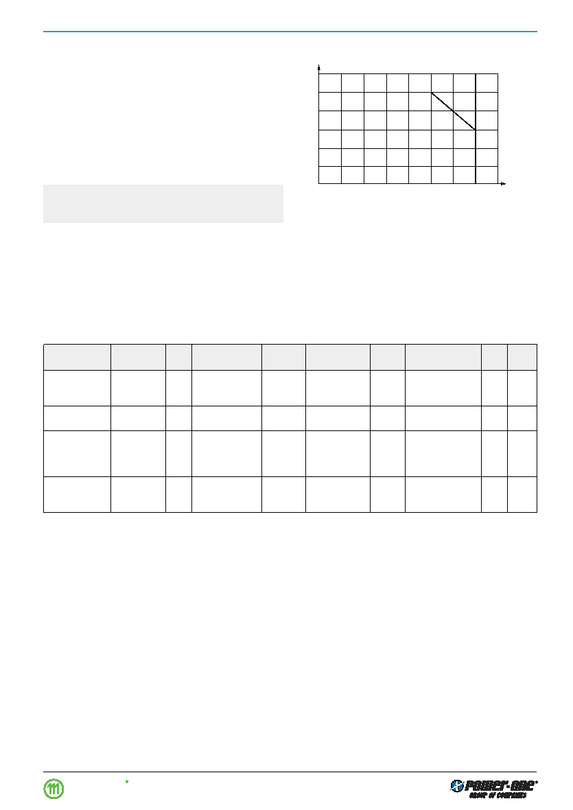
Fig. 3
Output power vs. ambient temperature
1.2
1.0
0.8
0.6
0.4
0
10
20
60
70
0.2
40
50
Po/Po max
TA [°C]
30
–10
0
05118
Thermal Considerations
The relation between the maximum allowed output power
Po allwed, the temperature TA of the surrounding air and the
mounting method is given in the:
Installation Instruction.
The percentage rates apply if the AC-DC converter is lo-
cated in free, quasi-stationary air (convection cooling).
The following figure shows the allowed output power of an
AC-DC converter if mounting method A is used.
For
Po max values see: Type Survey and Key Data. The ther-
mal conditions are influenced by input voltage, output cur-
rent, airflow and temperature of surrounding components
and surface.
Caution: The installer must ensure that under all operat-
ing conditions
TA remains within the limits stated in the
table.
Electromagnetic Compatibility (EMC)
Electromagnetic Immunity
A metal oxide VDR together with an input fuse and an input
filter form an effective protection against high input tran-
sient voltages which typically occur in most installations,
but especially in battery driven mobile applications. The
VEW series has been successfully tested to the following
specifications:
Table 5: Immunity type tests
Phenomenon
Standard 4
Level
Coupling
Value
Waveform
Source
Test
In
Per-
mode 3
applied
Imped.
procedure
oper. form.
Electrostatic
IEC/EN
x
air discharge
6000 Vp
1/50 ns
330
10 positive and
yes
1
discharge
61000-4-2
to frame
10 negative
discharges
Electromagnetic
IEC/EN
x
antenna in
10 V/m
sine wave mod-
26...1000 MHz
yes
1
field
61000-4-3
1 m distance
ulated w. 1 Hz
Electrical fast
IEC/EN
x
i/c, +i/–i
2000 Vp
5/50 ns
50
1 min positive
yes
1
transient/burst
61000-4-4
1 min negative
bursts per
coupling mode
Surge
IEC/EN
x
i/c
2000 Vp
1.2/50
s
12
5 pos. and 5 neg.
yes 21
61000-4-5
surges per
coupling mode
1 Normal operation, no deviation from specifications.
2 No load.
3 i = input, o = output, c = case.
4 For related and previous standards see: Technical Information: EMC.
相關(guān)PDF資料 |
PDF描述 |
|---|---|
| LW50-21 | 3-OUTPUT 51 W AC-DC REG PWR SUPPLY MODULE |
| LW100-51 | 4-OUTPUT 100 W AC-DC REG PWR SUPPLY MODULE |
| LWN1801-6RKF | 1-OUTPUT 240 W AC-DC PWR FACTOR CORR MODULE |
| LWN1601-6RKF | 1-OUTPUT 240 W AC-DC PWR FACTOR CORR MODULE |
| LWN1801-6RKF | 1-OUTPUT 240 W AC-DC PWR FACTOR CORR MODULE |
相關(guān)代理商/技術(shù)參數(shù) |
參數(shù)描述 |
|---|---|
| LW160Z | 制造商:SEOUL 制造商全稱:Seoul Semiconductor 功能描述:GREEN OVAL LAMP LED |
| LW161 | 制造商:SEOUL 制造商全稱:Seoul Semiconductor 功能描述:BLUE OVAL LAMP LED |
| LW170Z | 制造商:SEOUL 制造商全稱:Seoul Semiconductor 功能描述:GREEN OVAL LAMP LED |
| LW171 | 制造商:SEOUL 制造商全稱:Seoul Semiconductor 功能描述:BLUE OVAL LAMP LED |
| LW-18 (10/BAG) | 制造商:TURCK Inc 功能描述:Hardware, Lockwasher, M18 (10/BAG), Chrome Plated Brass, For 18mm Barrel, A3128 |
發(fā)布緊急采購,3分鐘左右您將得到回復(fù)。