- 您現(xiàn)在的位置:買賣IC網(wǎng) > PDF目錄45004 > LW030F81 (LINEAGE POWER LLC) 1-OUTPUT 19.8 W DC-DC REG PWR SUPPLY MODULE PDF資料下載
參數(shù)資料
| 型號: | LW030F81 |
| 廠商: | LINEAGE POWER LLC |
| 元件分類: | 電源模塊 |
| 英文描述: | 1-OUTPUT 19.8 W DC-DC REG PWR SUPPLY MODULE |
| 封裝: | MODULE-10 |
| 文件頁數(shù): | 4/16頁 |
| 文件大小: | 514K |
| 代理商: | LW030F81 |

12
Lineage Power
Data Sheet
April 2008
36 Vdc to 75 Vdc Inputs; 19.8 W to 30 W
LW030-Series Power Modules:
Thermal Considerations (continued)
Heat Transfer with Heat Sinks
The LW030-Series Power Modules include four
through-threaded M3 x 0.5 mounting holes, which
allow heat sinks or cold plates to be attached from
either side of the module. The mounting torque must
not exceed 0.56 N-m (5 in.-lb.).
Thermal derating with heat sinks is expressed through
use of the overall thermal resistance of the module.
Total module thermal resistance (
θCA) is defined as the
maximum case temperature rise (TC, max) divided by
the module power dissipation (PD):
θCA = TC, max/PD = (TC –TA)/PD
The location of the case temperature (TC) is defined in
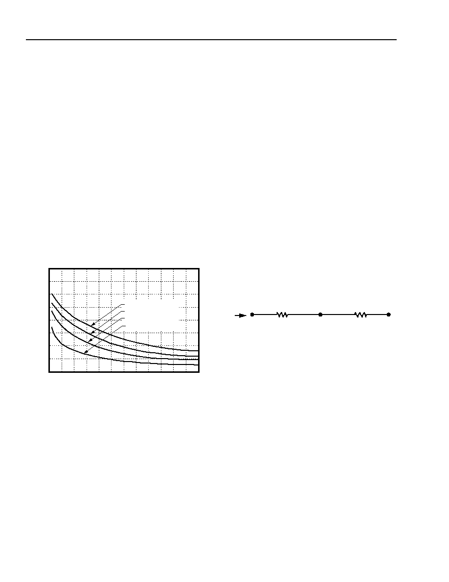
Figure 16. The case-to-ambient thermal resistance vs.
airflow for various heat sink configurations is given in
Figure 20. This set of curves was obtained by experi-
mental testing of heat sinks, which are offered in the
product catalog.
8-1157(C).b
Figure 20. LW030A and LW030F Case-to-Ambient
Thermal Resistance vs. Air Velocity
Curves; Either Orientation
These measured resistances are for heat transfer from
the sides and bottom of the module as well as the top
side with the attached heat sink; therefore, the case-to-
ambient thermal resistance shown is generally lower
than the resistance of the heat sink by itself. The mod-
ule used to collect the data in Figure 20 had a thermally
conductive dry pad between the case and the heat sink
to minimize contact resistance. Use of Figure 20 is
shown in the following example.
Example
Although the maximum case temperature for the
LW030A is 100 °C, one may want to limit the maximum
case temperature to a lower value for extremely high
reliability. If a 90 °C case temperature is desired, what
is the allowable minimum airflow necessary for an
LW030A operating at VI = 56 V and IO = 6 A with a
maximum ambient of 75 °C and a 1/2 in. heat sink?
Solution:
Given: VI = 56 V, IO = 6 A, TA = 75 °C, sink = 1/2 in.
θca = (TC – TA)/PD
= (90 – 75)/7.7
= 1.95 °C/W
Use Figure 20 to determine air velocity (1/2 in. heat
sink): v = 0.97 ms–1 (190 ft./min.)
Custom Heat Sinks
A more detailed model can be used to determine the
required thermal resistance of a heat sink to provide
necessary cooling. The total module resistance can be
separated into a resistance from case-to-sink (
θcs) and
sink-to-sink ambient (
θsa). This model is shown below.
Figure 21. Resistance from Case-to-Sink and
Sink-to-Ambient
For a managed interface using thermal grease or foils,
a value of
θcs = 0.1 °C/W – 0.3 °C/W is typical. Solu-
tion for the heat sink resistance is:
θsa = [(Tc – TA)/PD] – θcs
Note that this equation assumes that all dissipated
power must be shed by the heat sink. Depending on
the user-defined application environment, a more accu-
rate model including heat transfer from the sides and
bottom of the module can be used. This equation pro-
vides a conservative estimate in such instances.
Layout Considerations
Copper paths must not be routed beneath the power
module standoffs.
0
0.5
(100)
1.0
(200)
2.5
(500)
3.0
(600)
0
5
6
7
8
AIR VELOCITY ms-1 (ft./min.)
4
3
2
1
1.5
(300)
2.0
(400)
NO HEAT SINK
(1/4 in.) HEAT SINK
(1/2 in.) HEAT SINK
(1 in.) HEAT SINK
AMBIENT
THERMAL
RESIST
ANCE
(C/W)
PD
θcs
TA
TC
Ts
θca
sa
相關(guān)PDF資料 |
PDF描述 |
|---|---|
| LW030A7 | 1-OUTPUT 30 W DC-DC REG PWR SUPPLY MODULE |
| LW030A | 1-OUTPUT 30 W DC-DC REG PWR SUPPLY MODULE |
| LW030A1 | 1-OUTPUT 30 W DC-DC REG PWR SUPPLY MODULE |
| LW030A3 | 1-OUTPUT 30 W DC-DC REG PWR SUPPLY MODULE |
| LWN1301-6ERFK2G | DC-DC REG PWR SUPPLY MODULE |
相關(guān)代理商/技術(shù)參數(shù) |
參數(shù)描述 |
|---|---|
| LW04006K05M020 | 制造商:Molex 功能描述: |
| LW066A | 制造商:TI 制造商全稱:Texas Instruments 功能描述:QUADRUPLE BILATERAL ANALOG SWITCHES |
| LW1 | 制造商:TE Connectivity 功能描述: |
| LW-1 | 功能描述:打印機(jī) LS3E, Non-Laminated Label, Vinyl Cloth, RoHS:否 制造商:Seiko Instruments 產(chǎn)品:Printer 電源電壓: 每行點(diǎn)數(shù):9 x 320 打印速度:52.5 cps, 80 cps 紙張寬度:112 mm |
| LW10 | 功能描述:電位計(jì) 5W 10 OHM WW POT RoHS:否 制造商:Bourns 產(chǎn)品:Musical Syst Potentiometer 安裝風(fēng)格:Panel 錐度:Audio, Linear 轉(zhuǎn)數(shù): 電阻:500 kOhms 元件類型:Carbon 軸類型:Round / Plain 端接類型:Solder Lug 電壓額定值:200 V 功率額定值:0.2 W 容差:20 % |
發(fā)布緊急采購,3分鐘左右您將得到回復(fù)。