- 您現(xiàn)在的位置:買賣IC網(wǎng) > PDF目錄45004 > LW030A3 (LINEAGE POWER LLC) 1-OUTPUT 30 W DC-DC REG PWR SUPPLY MODULE PDF資料下載
參數(shù)資料
| 型號: | LW030A3 |
| 廠商: | LINEAGE POWER LLC |
| 元件分類: | 電源模塊 |
| 英文描述: | 1-OUTPUT 30 W DC-DC REG PWR SUPPLY MODULE |
| 封裝: | MODULE-10 |
| 文件頁數(shù): | 2/16頁 |
| 文件大小: | 514K |
| 代理商: | LW030A3 |

10
Lineage Power
Data Sheet
April 2008
36 Vdc to 75 Vdc Inputs; 19.8 W to 30 W
LW030-Series Power Modules:
Feature Descriptions (continued)
Output Voltage Adjustment (continued)
The combination of the output voltage adjustment and
sense range and the output voltage given in the Fea-
ture Specifications table cannot exceed 110% of the
nominal output voltage between the VO(+) and VO(–)
terminals.
The LW030-Series Power Modules have fixed current-
limit set points. Therefore, as the output voltage is
adjusted down, the available output power is reduced.
In addition, the minimum output current is a function of
the output voltage. As the output voltage is adjusted
down, the minimum required output current can
increase.
Output Overvoltage Protection
The output overvoltage clamp consists of control cir-
cuitry, independent of the primary regulation loop, that
monitors the voltage on the output terminals. The con-
trol loop of the protection circuit has a higher voltage
set point than the primary loop (see Feature Specifica-
tions table). In a fault condition, the overvoltage clamp
ensures that the output voltage does not exceed
VO, clamp, max. This provides a redundant voltage-control
that reduces the risk of output overvoltage.
Synchronization (Optional)
The unit is capable of external synchronization from an
independent time base with a switching rate between
290 kHz and 310 kHz. The amplitude of the synchro-
nizing pulse train is TTL compatible, and the duty cycle
ranges between 40% and 60%. Synchronization is ref-
erenced to the primary.
Thermal Considerations
Introduction
The LW030-Series Power Modules operate in a variety
of thermal environments; however, sufficient cooling
should be provided to help ensure reliable operation of
the unit. Heat-dissipating components inside the unit
are thermally coupled to the case. Heat is removed by
conduction, convection, and radiation to the surround-
ing environment. Proper cooling can be verified by
measuring the case temperature. Peak temperature
The temperature at this location should not exceed
100 °C. The output power of the module should not
exceed the rated power for the module as listed in the
Ordering Information table.
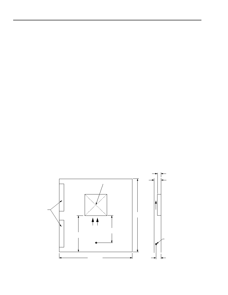
8-1046(C)
Note: Dimensions are in millimeters and (inches). Drawing is not to scale.
Figure 16. Thermal Test Setup
76.2
(3.00)
101.6
(4.00)
203.2 (8.00)
AIRFLOW
MEASURE CASE
TEMPERATURE (TC) AT
CENTER OF UNIT
CONNECTORS TO
LOADS, POWER
SUPPLIES, AND
DATALOGGER,
6.35 (0.25) TALL
19.1 (0.75)
12.7 (0.50)
AIR VELOCITY
AND AMBIENT
TEMPERATURE
MEASURED
BELOW THE
MODULE
AIR-
FLOW
WIND TUNNEL
WALL
203.2
(8.00)
相關(guān)PDF資料 |
PDF描述 |
|---|---|
| LWN1301-6ERFK2G | DC-DC REG PWR SUPPLY MODULE |
| LWR1801-6ERFK2G | DC-DC REG PWR SUPPLY MODULE |
| LWN2660-6ED5FK2G | DC-DC REG PWR SUPPLY MODULE |
| LWN2660-6EM2FK2G | DC-DC REG PWR SUPPLY MODULE |
| LWN1601-6ERFK2G | DC-DC REG PWR SUPPLY MODULE |
相關(guān)代理商/技術(shù)參數(shù) |
參數(shù)描述 |
|---|---|
| LW030A87 | 功能描述:CONVERTER DC/DC 5V 30W OUT RoHS:否 類別:電源 - 板載 >> DC DC Converters 系列:LW030 設(shè)計(jì)資源:VI-200, VI-J00 Design Guide, Appl Manual 標(biāo)準(zhǔn)包裝:1 系列:* 類型:隔離 輸出數(shù):1 電壓 - 輸入(最?。?42V 電壓 - 輸入(最大):60V Voltage - Output 1:15V Voltage - Output 2:- Voltage - Output 3:- 電流 - 輸出(最大):* 電源(瓦) - 制造商系列:150W 電壓 - 隔離:* 特點(diǎn):* 安裝類型:通孔 封裝/外殼:9-SlimMod 尺寸/尺寸:4.60" L x 1.80" W x 0.52" H(116.8mm x 45.7mm x 13.2mm) 包裝:散裝 工作溫度:-55°C ~ 85°C 效率:* 電源(瓦特)- 最大:* |
| LW04006K05M020 | 制造商:Molex 功能描述: |
| LW066A | 制造商:TI 制造商全稱:Texas Instruments 功能描述:QUADRUPLE BILATERAL ANALOG SWITCHES |
| LW1 | 制造商:TE Connectivity 功能描述: |
| LW-1 | 功能描述:打印機(jī) LS3E, Non-Laminated Label, Vinyl Cloth, RoHS:否 制造商:Seiko Instruments 產(chǎn)品:Printer 電源電壓: 每行點(diǎn)數(shù):9 x 320 打印速度:52.5 cps, 80 cps 紙張寬度:112 mm |
發(fā)布緊急采購,3分鐘左右您將得到回復(fù)。