- 您現(xiàn)在的位置:買賣IC網(wǎng) > PDF目錄224114 > LTC1435CG#TRPBF (LINEAR TECHNOLOGY CORP) High Efficiency Low Noise Synchronous Step-Down Switching Regulator PDF資料下載
參數(shù)資料
| 型號: | LTC1435CG#TRPBF |
| 廠商: | LINEAR TECHNOLOGY CORP |
| 元件分類: | 穩(wěn)壓器 |
| 英文描述: | High Efficiency Low Noise Synchronous Step-Down Switching Regulator |
| 中文描述: | 2 A SWITCHING CONTROLLER, 400 kHz SWITCHING FREQ-MAX, PDSO16 |
| 封裝: | 0.209 INCH, PLASTIC, SSOP-16 |
| 文件頁數(shù): | 6/20頁 |
| 文件大小: | 338K |
| 代理商: | LTC1435CG#TRPBF |
14
LTC1435
APPLICATIONS INFORMATION
WU
U
only solution is to limit the rise time of the switch drive so
that the load rise time is limited to approximately
(25)(CLOAD). Thus a 10F capacitor would require a 250s
rise time, limiting the charging current to about 200mA.
Automotive Considerations:
Plugging into the Cigarette Lighter
As battery-powered devices go mobile, there is a natural
interest in plugging into the cigarette lighter in order to
conserve or even recharge battery packs during operation.
But before you connect, be advised: you are plugging into
the supply from hell. The main battery line in an automo-
bile is the source of a number of nasty potential transients,
including load dump, reverse battery and double battery.
Load dump is the result of a loose battery cable. When the
cable breaks connection, the field collapse in the alternator
can cause a positive spike as high as 60V which takes
several hundred milliseconds to decay. Reverse battery is
just what it says, while double battery is a consequence of
tow truck operators finding that a 24V jump start cranks
cold engines faster than 12V.
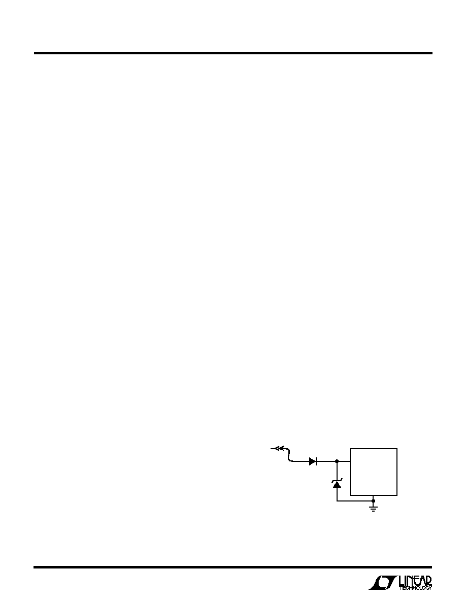
The network shown in Figure 7 is the most straightfor-
ward approach to protect a DC/DC converter from the
ravages of an automotive battery line. The series diode
prevents current from flowing during reverse battery,
while the transient suppressor clamps the input voltage
during load dump. Note that the transient suppressor
should not conduct during double battery operation, but
must still clamp the input voltage below breakdown of the
converter. Although the LT1435 has a maximum input
voltage of 36V, most applications will be limited to 30V
by the MOSFET BVDSS.
MOSFET and the synchronous MOSFET. If the two
MOSFETs have approximately the same RDS(ON), then
the resistance of one MOSFET can simply be summed
with the resistances of L and RSENSE to obtain I2R
losses. For example, if each RDS(ON) = 0.05,
RL = 0.15, and RSENSE = 0.05, then the total
resistance is 0.25
. This results in losses ranging
from 3% to 10% as the output current increases from
0.5A to 2A. I2R losses cause the efficiency to drop at
high output currents.
4. Transition losses apply only to the topside MOSFET(s),
and only when operating at high input voltages (typi-
cally 20V or greater). Transition losses can be esti-
mated from:
Transition Loss = 2.5 (VIN)
1.85(IMAX)(CRSS)(f)
Other losses, including CIN and COUT ESR dissipative
losses, Schottky conduction losses during dead-time,
and inductor core losses, generally account for less
than 2% total additional loss.
Checking Transient Response
The regulator loop response can be checked by looking at
the load transient response. Switching regulators take
several cycles to respond to a step in DC (resistive) load
current. When a load step occurs, VOUT immediately shifts
by an amount equal to (
ILOAD)(ESR), where ESR is the
effective series resistance of COUT. ILOAD also begins to
charge or discharge COUT which generates a feedback
error signal. The regulator loop then acts to return VOUT to
its steady-state value. During this recovery time VOUT can
be monitored for overshoot or ringing which would indi-
cate a stability problem. The ITH external components
shown in the Figure 1 circuit will provide adequate com-
pensation for most applications.
A second, more severe transient is caused by switching in
loads with large (>1
F) supply bypass capacitors. The
discharged bypass capacitors are effectively put in paral-
lel with COUT, causing a rapid drop in VOUT. No regulator
can deliver enough current to prevent this problem if the
load switch resistance is low and it is driven quickly. The
Figure 7. Automotive Application Protection
1435 F07
50A IPK RATING
LTC1435
TRANSIENT VOLTAGE
SUPPRESSOR
GENERAL INSTRUMENT
1.5KA24A
VIN
12V
相關(guān)PDF資料 |
PDF描述 |
|---|---|
| LTC1435CS#TRPBF | High Efficiency Low Noise Synchronous Step-Down Switching Regulator |
| LTC1435IG#PBF | High Efficiency Low Noise Synchronous Step-Down Switching Regulator |
| LTC1435IG#TRPBF | High Efficiency Low Noise Synchronous Step-Down Switching Regulator |
| LTC1436AEGN#PBF | RADIATION HARDENED HIGH EFFICIENCY, 5 AMP SWITCHING REGULATORS |
| LTC2249CUH#TR | 14-Bit, 80Msps Low Power 3V ADC; Package: QFN; No of Pins: 32; Temperature Range: 0°C to +70°C |
相關(guān)代理商/技術(shù)參數(shù) |
參數(shù)描述 |
|---|---|
| LTC1435CS | 功能描述:IC REG CTRLR BUCK PWM CM 16-SOIC RoHS:否 類別:集成電路 (IC) >> PMIC - 穩(wěn)壓器 - DC DC 切換控制器 系列:- 標準包裝:2,500 系列:- PWM 型:電流模式 輸出數(shù):1 頻率 - 最大:500kHz 占空比:96% 電源電壓:4 V ~ 36 V 降壓:無 升壓:是 回掃:無 反相:無 倍增器:無 除法器:無 Cuk:無 隔離:無 工作溫度:-40°C ~ 125°C 封裝/外殼:24-WQFN 裸露焊盤 包裝:帶卷 (TR) |
| LTC1435CS#PBF | 功能描述:IC REG CTRLR BUCK PWM CM 16-SOIC RoHS:是 類別:集成電路 (IC) >> PMIC - 穩(wěn)壓器 - DC DC 切換控制器 系列:- 標準包裝:4,500 系列:PowerWise® PWM 型:控制器 輸出數(shù):1 頻率 - 最大:1MHz 占空比:95% 電源電壓:2.8 V ~ 5.5 V 降壓:是 升壓:無 回掃:無 反相:無 倍增器:無 除法器:無 Cuk:無 隔離:無 工作溫度:-40°C ~ 125°C 封裝/外殼:6-WDFN 裸露焊盤 包裝:帶卷 (TR) 配用:LM1771EVAL-ND - BOARD EVALUATION LM1771 其它名稱:LM1771SSDX |
| LTC1435CS#TR | 制造商:Linear Technology 功能描述:DC DC Cntrlr Single-OUT Sync Step Down 3.5V to 36V Input 16-Pin SOIC N T/R |
| LTC1435CS#TRPBF | 功能描述:IC REG CTRLR BUCK PWM CM 16-SOIC RoHS:是 類別:集成電路 (IC) >> PMIC - 穩(wěn)壓器 - DC DC 切換控制器 系列:- 標準包裝:2,500 系列:- PWM 型:電流模式 輸出數(shù):1 頻率 - 最大:500kHz 占空比:96% 電源電壓:4 V ~ 36 V 降壓:無 升壓:是 回掃:無 反相:無 倍增器:無 除法器:無 Cuk:無 隔離:無 工作溫度:-40°C ~ 125°C 封裝/外殼:24-WQFN 裸露焊盤 包裝:帶卷 (TR) |
| LTC1435IG | 功能描述:IC REG CTRLR BUCK PWM CM 16-SSOP RoHS:否 類別:集成電路 (IC) >> PMIC - 穩(wěn)壓器 - DC DC 切換控制器 系列:- 標準包裝:4,500 系列:PowerWise® PWM 型:控制器 輸出數(shù):1 頻率 - 最大:1MHz 占空比:95% 電源電壓:2.8 V ~ 5.5 V 降壓:是 升壓:無 回掃:無 反相:無 倍增器:無 除法器:無 Cuk:無 隔離:無 工作溫度:-40°C ~ 125°C 封裝/外殼:6-WDFN 裸露焊盤 包裝:帶卷 (TR) 配用:LM1771EVAL-ND - BOARD EVALUATION LM1771 其它名稱:LM1771SSDX |
發(fā)布緊急采購,3分鐘左右您將得到回復(fù)。