- 您現(xiàn)在的位置:買賣IC網(wǎng) > PDF目錄67757 > LT3573IMSE#PBF (LINEAR TECHNOLOGY CORP) 1.85 A SWITCHING REGULATOR, 1000 kHz SWITCHING FREQ-MAX, PDSO16 PDF資料下載
參數(shù)資料
| 型號: | LT3573IMSE#PBF |
| 廠商: | LINEAR TECHNOLOGY CORP |
| 元件分類: | 穩(wěn)壓器 |
| 英文描述: | 1.85 A SWITCHING REGULATOR, 1000 kHz SWITCHING FREQ-MAX, PDSO16 |
| 封裝: | LEAD FREE, PLASTIC, MSOP-16 |
| 文件頁數(shù): | 6/26頁 |
| 文件大?。?/td> | 1182K |
| 代理商: | LT3573IMSE#PBF |
LT3573
3573fc
Secondary Leakage Inductance
In addition to the previously described effects of leakage
inductance in general, leakage inductance on the second-
ary in particular exhibits an additional phenomenon. It
forms an inductive divider on the transformer secondary
that effectively reduces the size of the primary-referred
flyback pulse used for feedback. This will increase the
output voltage target by a similar percentage. Note that
unlike leakage spike behavior, this phenomenon is load
independent. To the extent that the secondary leakage
inductance is a constant percentage of mutual inductance
(overmanufacturingvariations),thiscanbeaccommodated
by adjusting the RFB/RREF resistor ratio.
Winding Resistance Effects
Resistance in either the primary or secondary will reduce
overall efficiency (POUT/PIN). Good output voltage regula-
tion will be maintained independent of winding resistance
due to the boundary mode operation of the LT3573.
Bifilar Winding
A bifilar, or similar winding technique, is a good way to
minimize troublesome leakage inductances. However, re-
member that this will also increase primary-to-secondary
capacitanceandlimittheprimary-to-secondarybreakdown
voltage, so, bifilar winding is not always practical. The
Linear Technology applications group is available and
extremely qualified to assist in the selection and/or design
of the transformer.
Setting the Current Limit Resistor
The maximum current limit can be set by placing a resistor
between the RILIM pin and ground. This provides some
flexibilityinpickingstandardoff-the-shelftransformersthat
may be rated for less current than the LT3573’s internal
power switch current limit. If the maximum current limit
is needed, use a 10k resistor. For lower current limits, the
following equation sets the approximate current limit:
R
A I
k
ILIM
LIM
=
+
65 10 1 6
10
3
( .
)
The Switch Current Limit vs RILIM plot in the Typical Per-
formance Characteristics section depicts a more accurate
current limit.
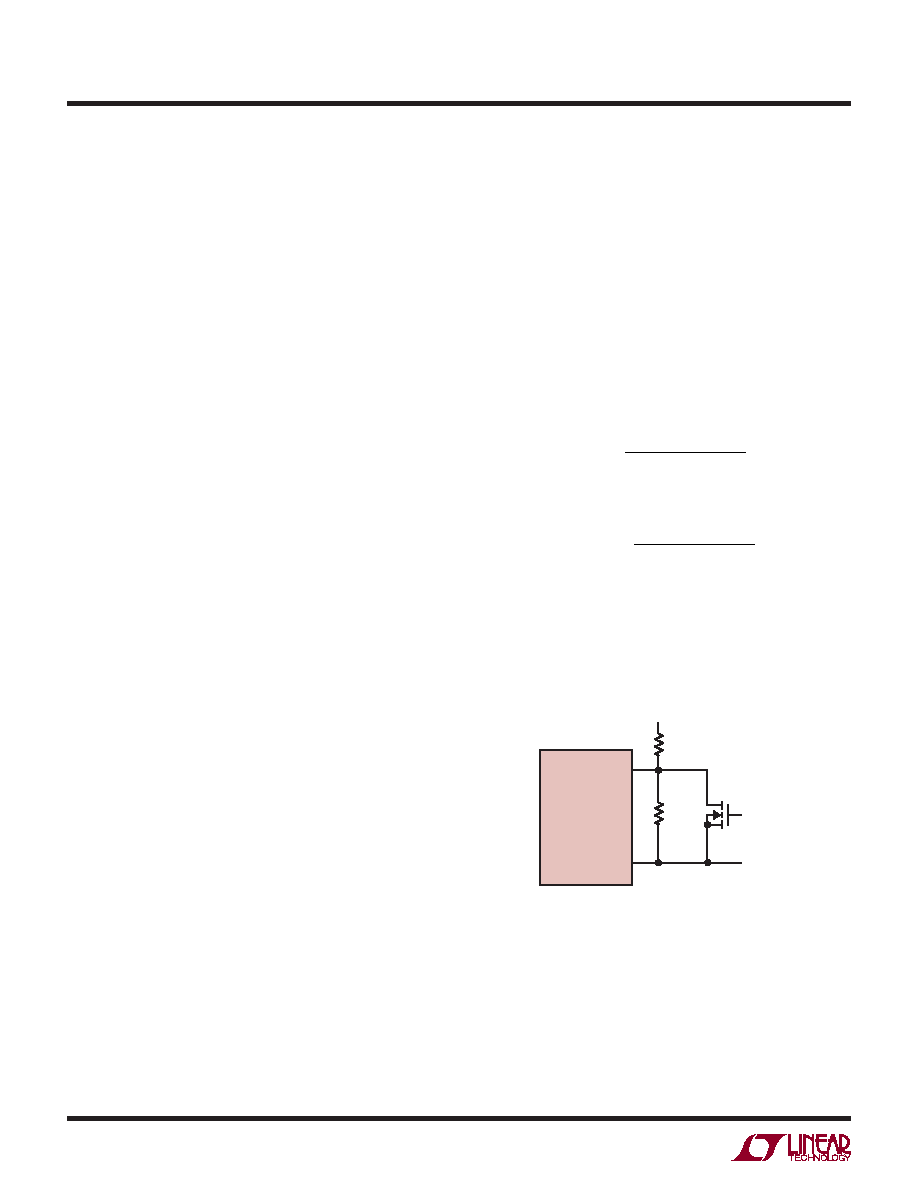
Undervoltage Lockout (UVLO)
The SHDN/UVLO pin is connected to a resistive voltage
divider connected to VIN as shown in Figure 8. The voltage
threshold on the SHDN/UVLO pin for VIN rising is 1.22V.
To introduce hysteresis, the LT3573 draws 2.5A from the
SHDN/UVLOpinwhenthepinisbelow1.22V.Thehysteresis
is therefore user-adjustable and depends on the value of
R1. The UVLO threshold for VIN rising is:
V
V R R
R
A R
IN UVLO RISING
(
,
)
.
(
)
.
=
+
1 22
1
2
2 5
1
The UVLO threshold for VIN falling is:
V
V R R
R
IN UVLO FALLING
(
,
)
.
(
)
=
+
1 22
1
2
To implement external run/stop control, connect a small
NMOS to the UVLO pin, as shown in Figure 8. Turning the
NMOS on grounds the UVLO pin and prevents the LT3573
from operating, and the part will draw less than a 1A of
quiescent current.
Figure 8. Undervoltage Lockout (UVLO)
LT3573
SHDN/UVLO
GND
R2
R1
VIN
3573 F08
RUN/STOP
CONTROL
(OPTIONAL)
applications inForMation
相關(guān)PDF資料 |
PDF描述 |
|---|---|
| LT3573EMSE#PBF | 1.85 A SWITCHING REGULATOR, 1000 kHz SWITCHING FREQ-MAX, PDSO16 |
| LT3573IMSE#TRPBF | 1.85 A SWITCHING REGULATOR, 1000 kHz SWITCHING FREQ-MAX, PDSO16 |
| LT3581EDE#PBF | SWITCHING REGULATOR, PDSO14 |
| LT3581EDE#TRPBF | SWITCHING REGULATOR, PDSO14 |
| LT3581EMSE#PBF | SWITCHING REGULATOR, PDSO16 |
相關(guān)代理商/技術(shù)參數(shù) |
參數(shù)描述 |
|---|---|
| LT3573IMSETRPBF | 制造商:LINER 制造商全稱:Linear Technology 功能描述:Isolated Flyback Converter without an Opto-Coupler |
| LT3573IMSE-TRPBF | 制造商:LINER 制造商全稱:Linear Technology 功能描述:Isolated Flyback Converter Without an Opto-Coupler |
| LT3574 | 制造商:LINER 制造商全稱:Linear Technology 功能描述:Isolated Flyback Converter Without an Opto-Coupler |
| LT3574EMS | 制造商:LINER 制造商全稱:Linear Technology 功能描述:Isolated Flyback Converter Without an Opto-Coupler |
| LT3574EMS#PBF | 功能描述:IC REG FLYBK ISO ADJ .65A 16MSOP RoHS:是 類別:集成電路 (IC) >> PMIC - 穩(wěn)壓器 - DC DC 開關(guān)穩(wěn)壓器 系列:- 標準包裝:250 系列:- 類型:降壓(降壓) 輸出類型:固定 輸出數(shù):1 輸出電壓:1.2V 輸入電壓:2.05 V ~ 6 V PWM 型:電壓模式 頻率 - 開關(guān):2MHz 電流 - 輸出:500mA 同步整流器:是 工作溫度:-40°C ~ 85°C 安裝類型:表面貼裝 封裝/外殼:6-UFDFN 包裝:帶卷 (TR) 供應商設備封裝:6-SON(1.45x1) 產(chǎn)品目錄頁面:1032 (CN2011-ZH PDF) 其它名稱:296-25628-2 |
發(fā)布緊急采購,3分鐘左右您將得到回復。