- 您現(xiàn)在的位置:買(mǎi)賣(mài)IC網(wǎng) > PDF目錄44979 > LT1740-7Z (POWER-ONE INC) 1-OUTPUT 500 W AC-DC REG PWR SUPPLY MODULE PDF資料下載
參數(shù)資料
| 型號(hào): | LT1740-7Z |
| 廠商: | POWER-ONE INC |
| 元件分類(lèi): | 電源模塊 |
| 英文描述: | 1-OUTPUT 500 W AC-DC REG PWR SUPPLY MODULE |
| 文件頁(yè)數(shù): | 24/32頁(yè) |
| 文件大小: | 1000K |
| 代理商: | LT1740-7Z |
第1頁(yè)第2頁(yè)第3頁(yè)第4頁(yè)第5頁(yè)第6頁(yè)第7頁(yè)第8頁(yè)第9頁(yè)第10頁(yè)第11頁(yè)第12頁(yè)第13頁(yè)第14頁(yè)第15頁(yè)第16頁(yè)第17頁(yè)第18頁(yè)第19頁(yè)第20頁(yè)第21頁(yè)第22頁(yè)第23頁(yè)當(dāng)前第24頁(yè)第25頁(yè)第26頁(yè)第27頁(yè)第28頁(yè)第29頁(yè)第30頁(yè)第31頁(yè)第32頁(yè)

BCD20023 Rev. AA, 3-Sep-2008
Page 30 of 32
www.power-one.com
T Series Data Sheet
500 Watt AC-DC Converters
Temperature Sensors T
The T Series battery chargers exhibit a cell voltage selector
switch Z to set the required floating charge voltage at 20 °C
directly at the converter. If this Z switch is used, the 2.23 V/cell
sensor types should be selected in any case as a basis, and
the selection criteria are only the temperature coefficient and
the nominal voltage of the battery. For example, if a 24 V
battery is used, which has a cell voltage of 2.23 V and a cell
temperature coefficient of –3.5 mV/K, the sensor type is S24-
2.23-35-02. The setting on the Z switch should be 2.23.
Table 24: Type survey temperature sensors T
Nominal battery
Sensor type
Cell voltage
Temp. coefficient per cell
Cable length
voltage [V]
[V]
[mV/K]
[m]
24
S24-2.23-30-02
2.23
–3.0
2
24
S24-2.23-35-02
2.23
–3.5
2
24
S24-2.23-45-02
2.23
–4.5
2
36
S36-2.23-30-02
2.23
–3.0
2
36
S36-2.23-35-02
2.23
–3.5
2
36
S36-2.27-35-02
2.27
–3.5
2
48
S48-2.23-30-02
2.23
–3.0
2
48
S48-2.23-35-02
2.23
–3.5
2
48
S48-2.23-40-02
2.23
–4.0
2
48
S48-2.23-45-02
2.23
–4.5
2
48
S48-2.27-30-02
2.27
–3.0
2
48
S48-2.27-35-02
2.27
–3.5
2
48
S48-2.27-45-02
2.27
–4.5
2
For T Series converters without Z selector switch, a sensor
according to both criteria should be selected. In our example it
should be S24-2.23-35-02.
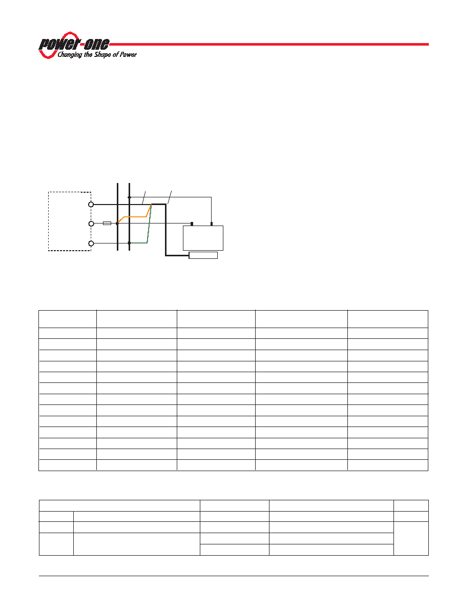
The active temperature sensor T is of robust construction,
mounted into a sealed aluminium tube of 12 mm outer
diameter and 50 mm length. The sensors are waterproof
(IP 66) and high-voltage tested with 1.4 kVDC. Connection
should be done via the colored 3 wire cable to the output of the
converter (Vo+ and Vo–) and the remote control input i/Vcr (pin
28).
Caution: Wrong connection may damage the sensor and the
converter.
Note: Battery specific sensors with cell voltages from 2.23 V up to
2.32 V and temperature coefficients from –2 up to –4.5 mV/K per
cell or different cable lengths are available upon request.
Note: For installation of batteries, see VDE 510 as well as the
recommendations of the battery manufacturers.
+
–
Battery
Vo+
i/Vcr
Vo–
Sensor
cable
Sensor
wires
+
05064b
green
brown
white
Fuse
–
22
12
28
Sensor T
Converter
Fig. 56
Wiring diagram sensor
Table 25: Sensor data
Characteristics
Condition
min
typ
max
Unit
Tsensor
Sensor temperature range
Vcr = 5.5 – 11.5 V
–10
60
°C
Vcr
Control voltage range
Absolute ratings
3.9
15
V
Vcr td
Control voltage tolerance
Tsensor = 20 °C
±0.1
Tsensor = 0 – 53 °C
±0.2
相關(guān)PDF資料 |
PDF描述 |
|---|---|
| LT1241MJ8 | 1 A SWITCHING CONTROLLER, 500 kHz SWITCHING FREQ-MAX, CDIP8 |
| LT1245MJ8 | 1 A SWITCHING CONTROLLER, 500 kHz SWITCHING FREQ-MAX, CDIP8 |
| LT1241CJ8 | 1 A SWITCHING CONTROLLER, 500 kHz SWITCHING FREQ-MAX, CDIP8 |
| LT1242CJ8 | 1 A SWITCHING CONTROLLER, 500 kHz SWITCHING FREQ-MAX, CDIP8 |
| LT1241IN8#TRPBF | SWITCHING CONTROLLER, 500 kHz SWITCHING FREQ-MAX, PDIP8 |
相關(guān)代理商/技術(shù)參數(shù) |
參數(shù)描述 |
|---|---|
| LT1743 | 制造商:未知廠家 制造商全稱(chēng):未知廠家 功能描述:Optoelectronic |
| LT1750 | 制造商:Pulse 功能描述:LAN,E/C,2000V - Bulk |
| LT1754ET | 制造商:Linear Technology 功能描述: |
| LT1761 | 制造商:LINER 制造商全稱(chēng):Linear Technology 功能描述:45V VIN, Micropower, Low Noise, 100mA Low Dropout, Linear Regulator |
| LT1761_1 | 制造商:LINER 制造商全稱(chēng):Linear Technology 功能描述:100mA, Low Noise,LDO Micropower Regulators in SOT-23 |
發(fā)布緊急采購(gòu),3分鐘左右您將得到回復(fù)。