- 您現(xiàn)在的位置:買賣IC網(wǎng) > PDF目錄377671 > LT1128M (Linear Technology Corporation) Ultra Low Noise Precision High Speed Op Amps PDF資料下載
參數(shù)資料
| 型號(hào): | LT1128M |
| 廠商: | Linear Technology Corporation |
| 英文描述: | Ultra Low Noise Precision High Speed Op Amps |
| 中文描述: | 超低噪聲精密高速運(yùn)算放大器 |
| 文件頁(yè)數(shù): | 12/20頁(yè) |
| 文件大小: | 439K |
| 代理商: | LT1128M |
第1頁(yè)第2頁(yè)第3頁(yè)第4頁(yè)第5頁(yè)第6頁(yè)第7頁(yè)第8頁(yè)第9頁(yè)第10頁(yè)第11頁(yè)當(dāng)前第12頁(yè)第13頁(yè)第14頁(yè)第15頁(yè)第16頁(yè)第17頁(yè)第18頁(yè)第19頁(yè)第20頁(yè)
12
LT1028/LT1128
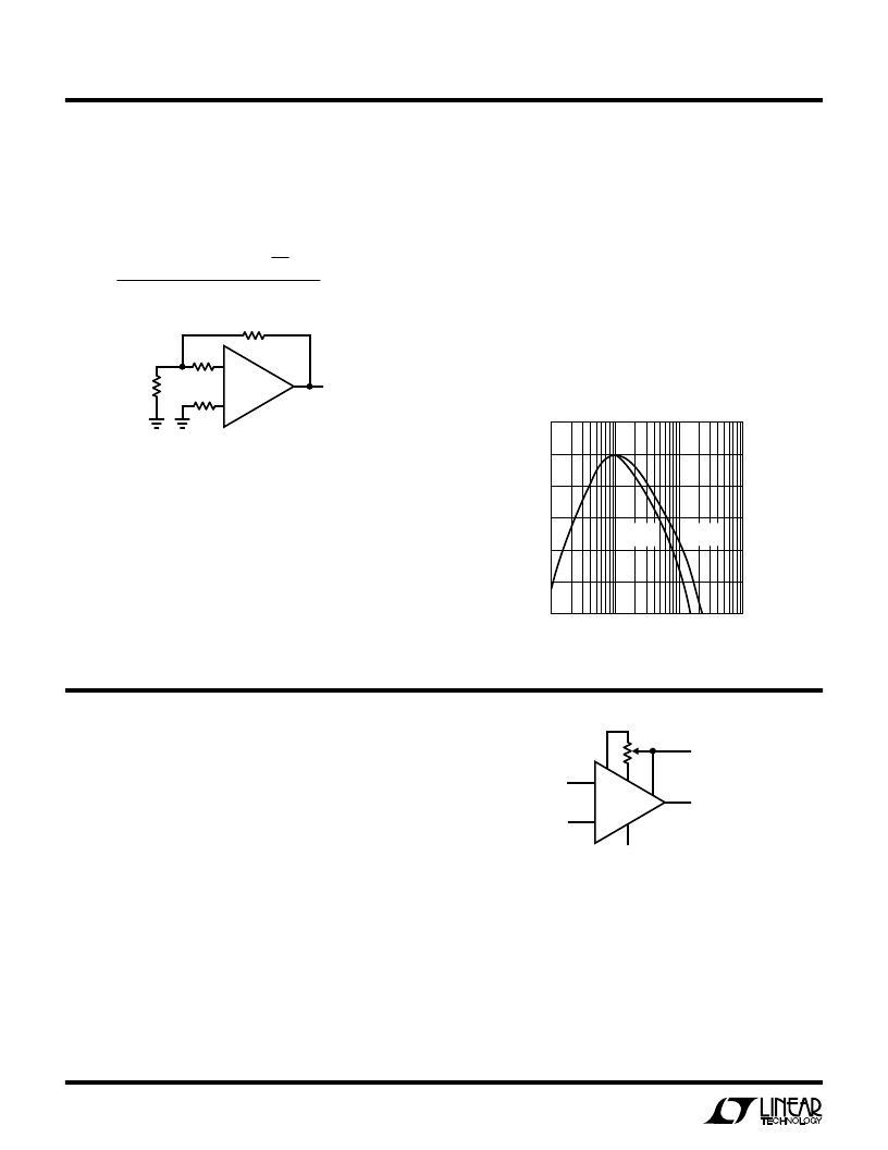
Noise Testing – Current Noise
Current noise density (I
n
) is defined by the following
formula, and can be measured in the circuit shown:
If the Quan Tech Model 5173 is used, the noise reading is
input-referred, therefore the result should not be divided
by 31; the resistor noise should not be multiplied by 31.
100% Noise Testing
The 1kHz voltage and current noise is 100% tested on the
LT1028/LT1128 as part of automated testing; the approxi-
mate frequency response of the filters is shown. The limits
on the automated testing are established by extensive
correlation tests on units measured with the Quan Tech
Model 5173.
U
S
A
O
PPLICATI
IU
U
10Hz voltage noise density is sample tested on every lot.
Devices 100% tested at 10Hz are available on request for
an additional charge.
10Hz current noise is not tested on every lot but it can be
inferred from 100% testing at 1kHz. A look at the current
noise spectrum plot will substantiate this statement. The
only way 10Hz current noise can exceed the guaranteed
limits is if its 1/f corner is higher than 800Hz and/or its
white noise is high. If that is the case then the 1kHz test will
fail.
I
n
= [e
no
2
– (31
×
18.4nV/
√
Hz)
2
]
1/2
20k
×
31
–
+
e
no
1.8k
60
LT1028
10k
10k
1028/1128 AI04
–U
FREQUENCY (Hz)
100
–50
N
–10
0
10
1k
10k
100k
LT1028/1128 AI05
–20
–40
–30
CURRENT
NOISE
VOLTAGE
NOISE
U
S
A
O
PPLICATI
U
U
General
The LT1028/LT1128 series devices may be inserted di-
rectly into OP-07, OP-27, OP-37, LT1007 and LT1037
sockets with or without removal of external nulling com-
ponents. In addition, the LT1028/LT1128 may be fitted to
5534 sockets with the removal of external compensation
components.
Offset Voltage Adjustment
The input offset voltage of the LT1028/LT1128 and its drift
with temperature, are permanently trimmed at wafer test-
ing to a low level. However, if further adjustment of V
OS
is
necessary, the use of a 1k nulling potentiometer will not
degrade drift with temperature. Trimming to a value other
Automated Tester Noise Filter
–
+
6
1k
INPUT
LT1028
1028/1128 AI06
7
8
1
2
3
4
OUTPUT
–15V
15V
than zero creates a drift of (V
OS
/300)
μ
V/
°
C, e.g., if V
OS
is
adjusted to 300
μ
V, the change in drift will be 1
μ
V/
°
C.
The adjustment range with a 1k pot is approximately
±
1.1mV.
Offset Voltage and Drift
Thermocouple effects, caused by temperature gradients
across dissimilar metals at the contacts to the input
相關(guān)PDF資料 |
PDF描述 |
|---|---|
| LT1028CJ8 | Ultra Low Noise Precision High Speed Op Amps |
| LT1128CJ8 | Ultra Low Noise Precision High Speed Op Amps |
| LT1030CN | Hex Noninverting Drivers 14-SO 0 to 70 |
| LT1030 | Hex Noninverting Drivers 14-SOIC 0 to 70 |
| LT1030CJ | Hex Noninverting Drivers 14-PDIP 0 to 70 |
相關(guān)代理商/技術(shù)參數(shù) |
參數(shù)描述 |
|---|---|
| LT1128MJ8 | 制造商:LINER 制造商全稱:Linear Technology 功能描述:Ultra Low Noise Precision High Speed Op Amps |
| LT1129 | 制造商:LINER 制造商全稱:Linear Technology 功能描述:500mA, Low Voltage, Very Low Dropout Linear Regulator |
| LT1129_1 | 制造商:LINEAR 制造商全稱:LINEAR 功能描述:Micropower Low Dropout Regulators with Shutdown |
| LT1129-3.3 | 制造商:LINER 制造商全稱:Linear Technology 功能描述:Micropower Low Dropout Regulators with Shutdown |
| LT1129-5 | 制造商:LINER 制造商全稱:Linear Technology 功能描述:Micropower Low Dropout Regulators with Shutdown |
發(fā)布緊急采購(gòu),3分鐘左右您將得到回復(fù)。