- 您現(xiàn)在的位置:買賣IC網(wǎng) > PDF目錄358953 > LT1054CN8 (LINEAR TECHNOLOGY CORP) Switched-Capacitor Voltage Converter with Regulator PDF資料下載
參數(shù)資料
| 型號(hào): | LT1054CN8 |
| 廠商: | LINEAR TECHNOLOGY CORP |
| 元件分類: | 穩(wěn)壓器 |
| 英文描述: | Switched-Capacitor Voltage Converter with Regulator |
| 中文描述: | SWITCHED CAPACITOR REGULATOR, 25 kHz SWITCHING FREQ-MAX, PDIP8 |
| 封裝: | 0.300 INCH, PLASTIC, DIP-8 |
| 文件頁(yè)數(shù): | 8/26頁(yè) |
| 文件大小: | 444K |
| 代理商: | LT1054CN8 |
第1頁(yè)第2頁(yè)第3頁(yè)第4頁(yè)第5頁(yè)第6頁(yè)第7頁(yè)當(dāng)前第8頁(yè)第9頁(yè)第10頁(yè)第11頁(yè)第12頁(yè)第13頁(yè)第14頁(yè)第15頁(yè)第16頁(yè)第17頁(yè)第18頁(yè)第19頁(yè)第20頁(yè)第21頁(yè)第22頁(yè)第23頁(yè)第24頁(yè)第25頁(yè)第26頁(yè)
SLVS033F FEBRUARY 1990 REVISED NOVEMBER 2004
8
POST OFFICE BOX 655303
DALLAS, TEXAS 75265
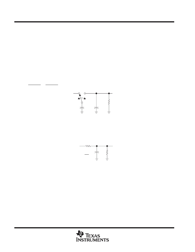
PRINCIPLES OF OPERATION
A review of a basic switched-capacitor building block is helpful in understanding the operation of the LT1054. When
the switch shown in Figure 12 is in the left position, capacitor C1 charges to the voltage at V1. The total charge on
C1 is q1 = C1V1. When the switch is moved to the right, C1 is discharged to the voltage at V2. After this discharge
time, the charge on C1 is q2 = C1V2. The charge has been transferred from the source V1 to the output V2. The
amount of charge transferred is shown in equation 1.
q
q1
q2
C1(V1
V2)
If the switch is cycled f times per second, the charge transfer per unit time (i.e., current) is as shown in equation 2.
I
f
q
f
C1(1
V2)
To obtain an equivalent resistance for a switched-capacitor network, this equation can be rewritten in terms of voltage
and impedance equivalence as shown in equation 3.
I
V1
V2
1 fC1
V1
V2
R
EQUIV
C2
C1
V2
f
V1
RL
Figure 12. Switched-Capacitor Building Block
A new variable, R
EQUIV
, is defined as R
EQUIV
= 1
÷
fC1. The equivalent circuit for the switched-capacitor network is
shown in Figure 13. The LT1054 has the same switching action as the basic switched-capacitor building block. Even
though this simplification does not include finite switch-on resistance and output-voltage ripple, it provides an insight
into how the device operates.
C2
V2
V1
RL
REQUIV
R
EQUIV
1
fC1
Figure 13. Switched-Capacitor Equivalent Circuit
These simplified circuits explain voltage loss as a function of oscillator frequency (see Figure 7). As oscillator
frequency is decreased, the output impedance eventually is dominated by the 1/fC1 term, and voltage losses rise.
Voltage losses also rise as oscillator frequency increases. This is caused by internal switching losses that occur due
to some finite charge being lost on each switching cycle. This charge loss per-unit-cycle, when multiplied by the
switching frequency, becomes a current loss. At high frequency, this loss becomes significant and voltage losses
again rise.
The oscillator of the LT1054 is designed to operate in the frequency band where voltage losses are at a minimum.
(1)
(2)
(3)
相關(guān)PDF資料 |
PDF描述 |
|---|---|
| LT1072 | 500kHz and 1MHz High Efficiency 1.5A Switching Regulators; Package: SO; No of Pins: 8; Temperature Range: -40?°C to 85?°C |
| LT10A01 | Quadruple D-Type Positive-Edge-Triggered Flip-Flops With Clear 16-SOIC 0 to 70 |
| LT120 | Hall Voltage 160mV GaAs Hall Device |
| LT1204CS | 4-Channel Analog Multiplexer |
| LT120A | Hall Voltage 160mV GaAs Hall Device |
相關(guān)代理商/技術(shù)參數(shù) |
參數(shù)描述 |
|---|---|
| LT1054CN8#PBF | 功能描述:IC REG SWITCHED CAP DBL INV 8DIP RoHS:是 類別:集成電路 (IC) >> PMIC - 穩(wěn)壓器 - DC DC 開(kāi)關(guān)穩(wěn)壓器 系列:- 標(biāo)準(zhǔn)包裝:250 系列:- 類型:降壓(降壓) 輸出類型:固定 輸出數(shù):1 輸出電壓:1.2V 輸入電壓:2.05 V ~ 6 V PWM 型:電壓模式 頻率 - 開(kāi)關(guān):2MHz 電流 - 輸出:500mA 同步整流器:是 工作溫度:-40°C ~ 85°C 安裝類型:表面貼裝 封裝/外殼:6-UFDFN 包裝:帶卷 (TR) 供應(yīng)商設(shè)備封裝:6-SON(1.45x1) 產(chǎn)品目錄頁(yè)面:1032 (CN2011-ZH PDF) 其它名稱:296-25628-2 |
| LT1054CN8PBF | 制造商:Linear Technology 功能描述:DC-DC converter,LT1054CN8 -Vin/2Vin 20mA |
| LT1054CP | 功能描述:電荷泵 Bipolar Regulated V RoHS:否 制造商:Maxim Integrated 功能:Inverting, Step Up 輸出電壓:- 1.5 V to - 5.5 V, 3 V to 11 V 輸出電流:100 mA 電源電流:1 mA 最大工作溫度:+ 70 C 封裝 / 箱體:SOIC-8 Narrow 封裝:Tube |
| LT1054CP | 制造商:Texas Instruments 功能描述:DC/DC Charge Pump Converter IC |
| LT1054CP | 制造商:Texas Instruments 功能描述:IC VOLT CONVERTER REG 100MA 8DIP 制造商:Texas Instruments 功能描述:IC, VOLT CONVERTER REG, 100MA, 8DIP 制造商:Texas Instruments 功能描述:IC, VOLT CONVERTER REG, 100MA, 8DIP; Primary Input Voltage:15V; No. of Outputs:1; Output Voltage:-5V; Output Current:100mA; Voltage Regulator Case Style:DIP; No. of Pins:8; Operating Temperature Min:0C; Operating Temperature ;RoHS Compliant: Yes |
發(fā)布緊急采購(gòu),3分鐘左右您將得到回復(fù)。