- 您現(xiàn)在的位置:買賣IC網(wǎng) > PDF目錄39391 > LSP3170SD (LITE-ON SEMICONDUCTOR CORP) SWITCHING REGULATOR, PDSO8 PDF資料下載
參數(shù)資料
| 型號(hào): | LSP3170SD |
| 廠商: | LITE-ON SEMICONDUCTOR CORP |
| 元件分類: | 穩(wěn)壓器 |
| 英文描述: | SWITCHING REGULATOR, PDSO8 |
| 封裝: | SOP-8 |
| 文件頁數(shù): | 3/10頁 |
| 文件大?。?/td> | 244K |
| 代理商: | LSP3170SD |
Liteon Semiconductor Corporation
LSP3170
2A Step Down DC/DC Converter
Rev1.5
2/10
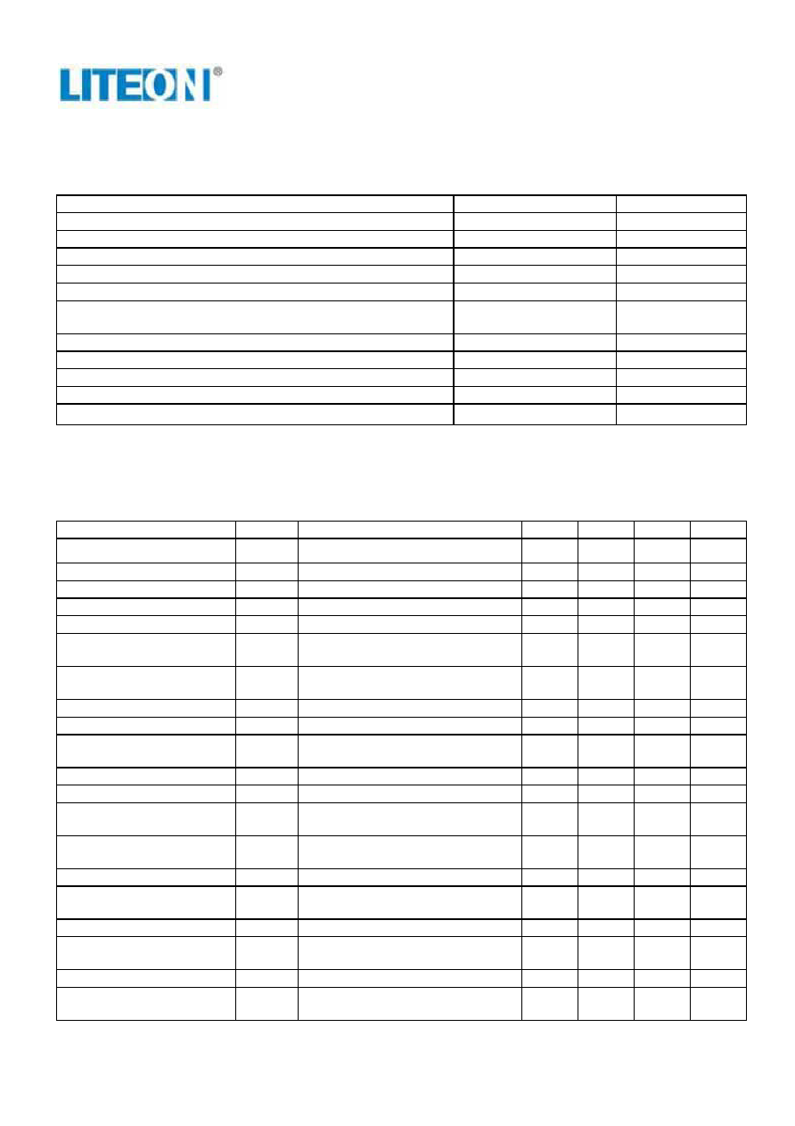
ABSOLUTE MAXIMUM RATINGS
Parameter
Value
Unit
IN Supply Voltage
-0.3 to 28
V
SW Voltage
-1 to VIN + 1
V
BS Voltage
VSW – 0.3 to VSW + 8
V
EN, FB, COMP Voltage
-0.3 to 7
V
Continuous SW Current
Internally limited
A
Junction to Ambient Thermal Resistance (θJA)
(Test on Approximately 3 in
2 Copper Area 1OZ copper FR4 board)
70
°C/W
Junction to Ambient Case Resistance (θJC)
20
°C/W
Maximum Power Dissipation
0.76
W
Operating Junction Temperature
-40 to 150
°C
Storage Temperature
-55 to 150
°C
Lead Temperature (Soldering, 10 sec)
300
°C
(Note: Exceeding these limits may damage the device. Exposure to absolute maximum rating conditions for long
periods may affect device reliability.)
ELECTRICAL CHARACTERISTICS
(VIN = 12V, TA= 25°C unless otherwise specified.)
Parameter
Symbol
Test Conditions
Min.
Typ.
Max.
Unit
Input Operating Voltage
VIN
VOUT = 1.2V, ILOAD = 0A to 2A
4.6
24
V
Input Holdup Voltage
VOUT = 1.2V, ILOAD = 0A to 2A
4.5
V
Feedback Voltage
VFB
4.6V ≤ VIN ≤ 24V, VCOMP = 1.5V
1.185
1.222
1.258
V
SW Leakage
VEN = 0
0
10
A
Current Limit
ILIMT
2.6
A
COMP to Current Limit
Transconductance
GCOMP
2.5
A/V
Error Amplifier
Transconductance
GEA
ICOMP = ±10A
850
A/V
Error Amplifier DC Gain
AVEA
350
V/V
Switching Frequency
fSW
350
400
470
kHz
Short Circuit Switching
Frequency
VFB = 0
50
kHz
Maximum Duty Cycle
DMAX
VFB = 1.1V
95
%
Minimum Duty Cycle
VFB = 1.4V
0
%
V COMP Pin Maximum
Switching Threshold
Duty cycle = 0%
0.35
V
Minimum Boost Voltage
Above Switch
ISW = 2A
1.8
2.7
V
Enable Threshold Voltage
Hysteresis = 0.1V
2.0
2.5
V
Enable Pull Up Current
Pin pulled up to 4.5V typically when
left unconnected
2
A
Supply Current in Shutdown
VEN = 0
15
40
A
IC Supply Current in
Operation
VEN = 3V, VFB = 1.4V
1.5
mA
IN Under Voltage Lockout
UVLO
3.9
V
Thermal Shutdown
Temperature
Hysteresis = 10°C
160
°C
相關(guān)PDF資料 |
PDF描述 |
|---|---|
| LSP3170SAD | SWITCHING REGULATOR, PDSO8 |
| LSS020-01GT | SIP20, IC SOCKET |
| LSS020-04GG | SIP20, IC SOCKET |
| LSS020-04GT | SIP20, IC SOCKET |
| LSS020-29GG | SIP20, IC SOCKET |
相關(guān)代理商/技術(shù)參數(shù) |
參數(shù)描述 |
|---|---|
| LSP32-K2-RGBA | 制造商:Dialight 功能描述:LED MODULE 32X K2 RGBA |
| LSP-32K2-RGBW | 制造商:Dialight 功能描述: |
| LSP32-K2-RGBW | 制造商:Dialight 功能描述:LED MODULE 32X K2 RGBW |
| LSP-32K2-WWWW | 制造商:Dialight 功能描述: |
| LSP32-K2-WWWW | 制造商:Dialight 功能描述:LED MODULE 32X K2 WWWW |
發(fā)布緊急采購,3分鐘左右您將得到回復(fù)。