- 您現(xiàn)在的位置:買賣IC網(wǎng) > PDF目錄377664 > LS7223 (LSI Corporation) KEYPAD PROGRAMMABLE DIGITAL LOCK PDF資料下載
參數(shù)資料
| 型號: | LS7223 |
| 廠商: | LSI Corporation |
| 英文描述: | KEYPAD PROGRAMMABLE DIGITAL LOCK |
| 中文描述: | 可編程數(shù)字鍵盤鎖 |
| 文件頁數(shù): | 2/4頁 |
| 文件大小: | 28K |
| 代理商: | LS7223 |
PROGRAM MODE
The current Primary/Secondary/Duress codes may be altered to
any value by initializing the Program Mode. The steps involved for
altering the codes are:
1. Enter the current Secondary code causing the Lock 2 output
to toggle.
2. Before the keypad entry enable time expires, enter the key
corresponding to matrix position X4 Y1 two times. This will
cause the Program Mode output to latch high, indicating that
the circuit is now in the Program mode. The keypad entry
enable timer is disabled during the Program mode.
3. Enter a 6-digit number from the keypad. The Program Mode
output will latch low, indicating that the new codes have
successfully been programmed. Of the 6 digits, the first 4
constitute the Primary code; the first 3 and the 5th constitute
the Secondary code and the first 3 and the 6th constitute the
Duress code. If an error is introduced or it is desired to
change the codes before the 6th digit is typed, enter the key
X4 Y3. This will reset the internal memory pointer of the
LS7223 and a new 6-digit number can be entered.
KEYPAD INTERFACE
The four X inputs and four Y outputs are designed for keypad
interface (see Fig. 2). Since the X inputs have internal pull-ups,
the maximum matrix size of 4 by 4 does not have to be utilized.
During normal operation, the LS7223 will scan the matrix look-
ing for a switch closure. Once a closure has been detected,
the internal key debounce logic determines if a "valid" key has
been pressed or that if noise is just present. Only one valid
input will be generated with any key closure. The use of
internal key debouncing and Schmitt triggers on the inputs
provides the LS7223 with very high noise immunity.
TAMPER
When a valid key has been detected by the LS7223, the entry
is compared against the appropriate reference in the internal
memory. If the requirements of digit value and code sequential
position are not fulfilled, the Tamper output will momentarily go
high; this indicates that an illegal code entry was attempted.
The keypad entry enable timer and memory pointer will both be
reset so that entry of the code can be attempted again.
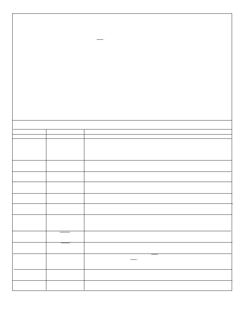
TABLE 1. PIN DESCRIPTIONS
PIN
1
2
FUNCTION
Vss
RC-OSC
DESCRIPTION
Supply voltage negative.
Determines the LS7223's internal clock frequency, which is used for keypad scanning and
debounce. A resistor (to V
DD
) and a capacitor (to Vss) connected to this input sets the
frequency. With a 1.5M
resistor and a 100pF capacitor, the internal frequency is typically
10KHz and the internal anti-bounce is typically 25ms.
The four X inputs and four Y outputs are designed to interface to a keypad matrix
whose maximum allowable size is 4 by 4.
This output goes high when the program mode is initiated. It resets to a low state after the 6-
digit Primary/Secondary/Duress combination code has been programmed.
A capacitor connected between this input and Vss controls the duration of the Momentary
and Tamper outputs.
Whenever a key is entered that is not a valid code element, this output goes high for a
period determined by the capacitor on the CAP-M input.
This output generates an active high output every time the Primary code is entered. The
duration of this output is determined by the capacitor on the CAP-M input.
When the Duress code is entered, this output latches high to enable an external alarm. The
Alarm output resets to a low state when the Primary code is entered again. This output pow-
ers-up to a low state.
Whenever the Secondary code is entered, this output toggles. The output powers-up into a
low state.
When ever the Primary code or the Duress code is entered, this output toggles. The output
powers-up into a low state.
Functionally, this output is identical to the Lock 1 output, with the exception that its polarity is
reversed with respect to the Lock 1 output. This output is intended for driving a display lamp
to indicate the lock status.
A capacitor connected between this input and Vss sets the time limit for entering a 4 digit
code from the keypad. (6 digits when initiating the Program Mode.)
Supply voltage positive.
3, 4, 5, 6
7, 8, 9, 10
11
X1, X2, X3, X4
Y1, Y2, Y3, Y4
PROGRAM MODE
12
CAP-M
13
TAMPER
14
MOMEMTARY
15
ALARM
16
LOCK 2
17
LOCK1
18
LOCK STATUS
19
CAP-K
20
V
DD
7223-013001-2
相關PDF資料 |
PDF描述 |
|---|---|
| LS7225 | DIGITAL LOCK CIRCUIT with Tamper Output |
| LS7226 | DIGITAL LOCK CIRCUIT with Tamper Output |
| LS7231 | TOUCH CONTROL LAMP DIMMER |
| LS7234 | TOUCH CONTROL LAMP DIMMER |
| LS7232ND | TOUCH CONTROL LAMP DIMMER |
相關代理商/技術參數(shù) |
參數(shù)描述 |
|---|---|
| LS7225 | 制造商:LSI 制造商全稱:LSI 功能描述:DIGITAL LOCK CIRCUIT with Tamper Output |
| LS7226 | 制造商:LSI 制造商全稱:LSI 功能描述:DIGITAL LOCK CIRCUIT with Tamper Output |
| LS7228 | 制造商:未知廠家 制造商全稱:未知廠家 功能描述:Address Decoder |
| LS7229 | 制造商:未知廠家 制造商全稱:未知廠家 功能描述:Address Decoder |
| LS7231 | 制造商:LSI 制造商全稱:LSI 功能描述:TOUCH CONTROL LAMP DIMMER |
發(fā)布緊急采購,3分鐘左右您將得到回復。