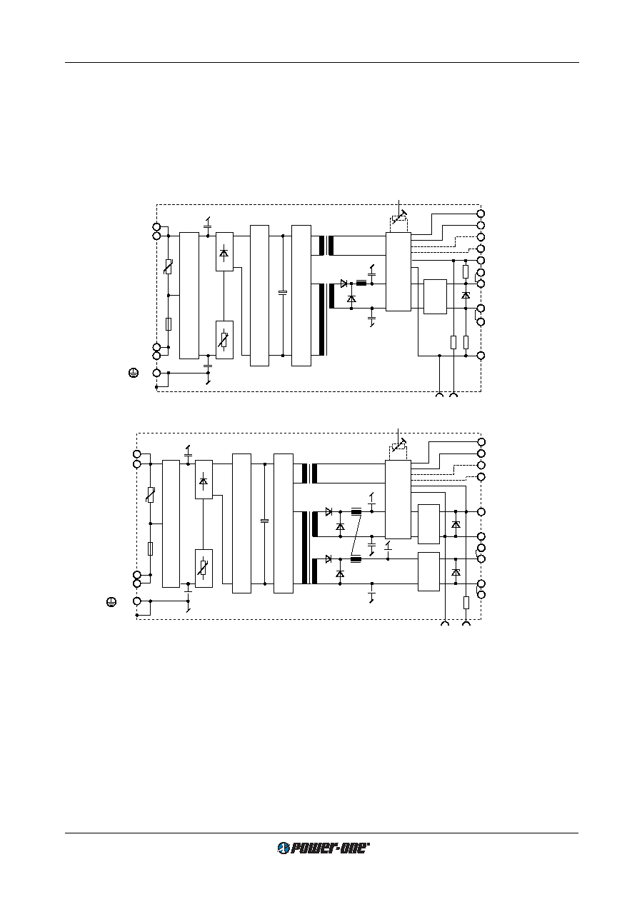
- 您現(xiàn)在的位置:買賣IC網(wǎng) > PDF目錄44949 > LS4501-9PD4T 1-OUTPUT 100 W AC-DC PWR FACTOR CORR MODULE PDF資料下載
參數(shù)資料
| 型號(hào): | LS4501-9PD4T |
| 元件分類: | 電源模塊 |
| 英文描述: | 1-OUTPUT 100 W AC-DC PWR FACTOR CORR MODULE |
| 封裝: | HEAT SINK, METAL, CASE S02, MODULE |
| 文件頁(yè)數(shù): | 21/27頁(yè) |
| 文件大小: | 599K |
| 代理商: | LS4501-9PD4T |
第1頁(yè)第2頁(yè)第3頁(yè)第4頁(yè)第5頁(yè)第6頁(yè)第7頁(yè)第8頁(yè)第9頁(yè)第10頁(yè)第11頁(yè)第12頁(yè)第13頁(yè)第14頁(yè)第15頁(yè)第16頁(yè)第17頁(yè)第18頁(yè)第19頁(yè)第20頁(yè)當(dāng)前第21頁(yè)第22頁(yè)第23頁(yè)第24頁(yè)第25頁(yè)第26頁(yè)第27頁(yè)
相關(guān)PDF資料 |
PDF描述 |
|---|---|
| LS4501-9PD4 | 1-OUTPUT 100 W AC-DC PWR FACTOR CORR MODULE |
| LS4501-9RD4 | 1-OUTPUT 100 W AC-DC PWR FACTOR CORR MODULE |
| LS4601-7EPD1TB2 | 1-OUTPUT 100 W AC-DC PWR FACTOR CORR MODULE |
| LS4601-7ERD1TB1 | 1-OUTPUT 100 W AC-DC PWR FACTOR CORR MODULE |
| LS4601-7PB1 | 1-OUTPUT 100 W AC-DC PWR FACTOR CORR MODULE |
相關(guān)代理商/技術(shù)參數(shù) |
參數(shù)描述 |
|---|---|
| LS4-53 | 制造商:Panduit Corp 功能描述: |
| LS4-54 | 制造商:Panduit Corp 功能描述: |
| LS-454/U | 制造商:undefined 功能描述: |
| LS454U | 制造商: 功能描述: 制造商:TELP 功能描述: 制造商:undefined 功能描述: |
| LS45-500 | 制造商:未知廠家 制造商全稱:未知廠家 功能描述:Analog IC |
發(fā)布緊急采購(gòu),3分鐘左右您將得到回復(fù)。
