- 您現(xiàn)在的位置:買賣IC網(wǎng) > PDF目錄377657 > LQH2MCN150K02 (Linear Technology Corporation) 20mA LED Driver and OLED Driver with Integrated Schottky in 3mm x 2mm DFN PDF資料下載
參數(shù)資料
| 型號: | LQH2MCN150K02 |
| 廠商: | Linear Technology Corporation |
| 英文描述: | 20mA LED Driver and OLED Driver with Integrated Schottky in 3mm x 2mm DFN |
| 中文描述: | 20mA的LED驅(qū)動器和3毫米的OLED驅(qū)動器集成肖特基x 2mm DFN封裝 |
| 文件頁數(shù): | 14/24頁 |
| 文件大?。?/td> | 449K |
| 代理商: | LQH2MCN150K02 |
LT3498
14
3498f
APPLICATIONS INFORMATION—OLED DRIVER
Inductor Selection
Several recommended inductors that work well with the
OLED driver of the LT3498 are listed in Table 5, although
there are many other manufacturers and devices that can
be used. Consult each manufacturer for more detailed
information and for their entire selection of related parts.
Many different sizes and shapes are available. Use the
equations and recommendations in the next few sections
to find the correct inductance value for your design.
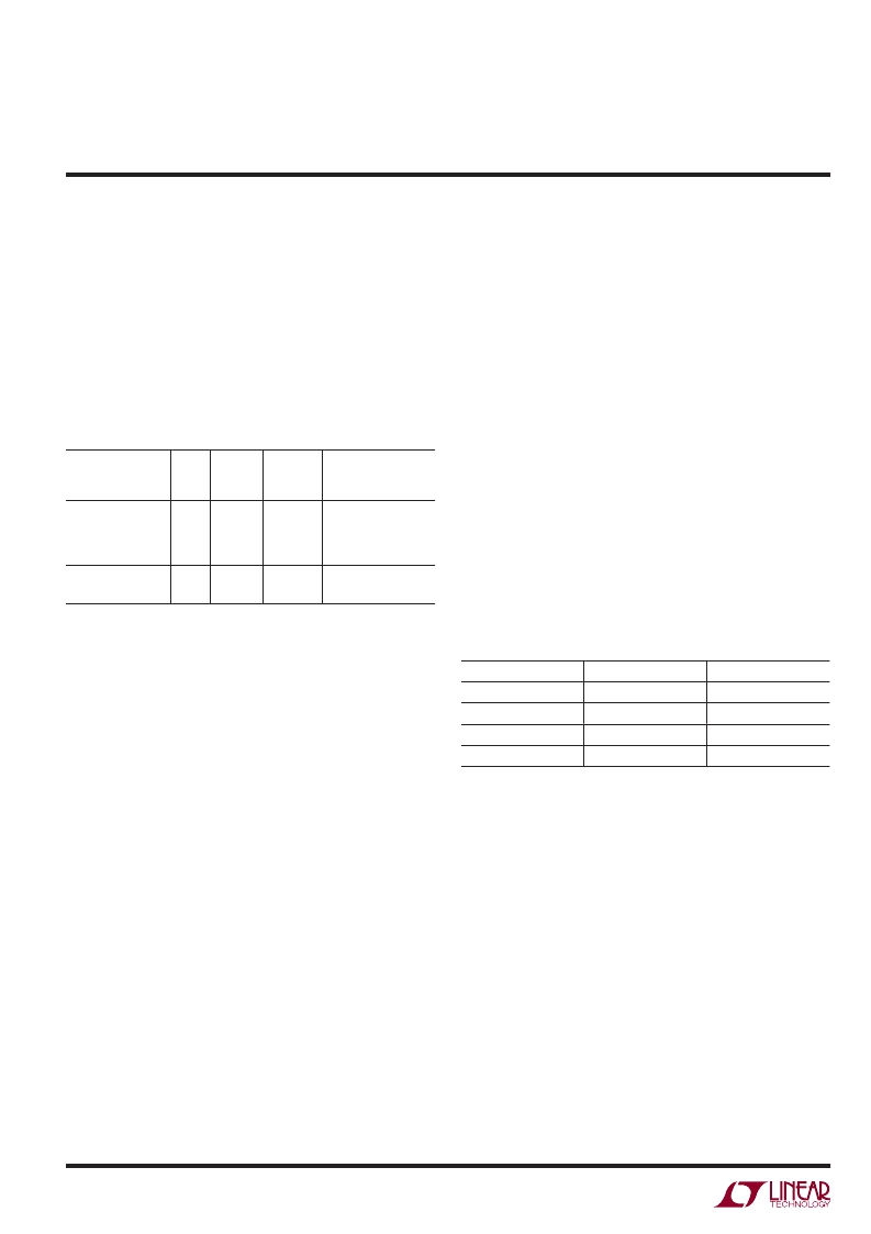
Table 5: Recommended Inductors
MAX
DCR
(
Ω
)
(mA)
LQH32CN100K53
LQH2MCN100K02
LQH32CN150K53
LQH2MCN150K02
15
1.6
200
SD3110-100
SD3110-150
15
0.764
380
PART
L
(μH)
10
10
15
CURRENT
RATING
VENDOR
Murata
www.murata.com
0.3
1.2
0.58
450
225
300
10
0.505
470
Cooper
www.cooperet.com
Inductor Selection—Boost Regulator
The formula below calculates the appropriate inductor
value to be used for the low noise boost regulator of
the LT3498 (or at least provides a good starting point).
This value provides a good tradeoff in inductor size and
system performance. Pick a standard inductor close to
this value. A larger value can be used to slightly increase
the available output current, but limit it to around twice
the value calculated below, as too large of an inductance
will decrease the output voltage ripple without providing
much additional output current. A smaller value can be
used (especially for systems with output voltages greater
than 12V) to give a smaller physical size. Inductance can
be calculated as:
where V
OUT2
is the desired output voltage and V
IN(MIN)
is
the minimum input voltage. Generally, a 10μH or 15μH
inductor is a good choice.
L
V
V
V
H
OUT
IN MIN
(
=
+
(
.
)0 66
(
)
)
2
0 5
μ
Capacitor Selection
The small size and low ESR of ceramic capacitors makes
them suitable for most OLED Driver applications. X5R and
X7R types are recommended because they retain their ca-
pacitance over wider voltage and temperature ranges than
other types such as Y5V or Z5U. A 4.7μF input capacitor
and a 10μF output capacitor are sufficient for most appli-
cations for the OLED Driver. Always use a capacitor with
a sufficient voltage rating. Many capacitors rated at 10μF,
particularly 0805 or 0603 case sizes, have greatly reduced
capacitance when bias voltages are applied. Be sure to check
actual capacitance at the desired output voltage. Generally
a 1206 size capacitor will be adequate. A 0.47μF capaci-
tor placed on the CAP node is recommended to filter the
inductor current while the larger 10μF placed on the V
OUT
node will give excellent transient response and stability.
Table 6 shows a list of several capacitor manufacturers.
Consult the manufacturers for more detailed information
and for their entire selection of related parts.
Table 6. Recommended Ceramic Capacitor Manufacturers
MANUFACTURER
PHONE
Taiyo Yuden
408-573-4150
AVX
843-448-9411
Murata
814-237-1431
Kemet
408-986-0424
URL
www.t-yuden.com
www.avxcorp.com
www.murata.com
www.kemet.com
Setting Output Voltage and the Auxiliary
Reference Input
The OLED driver of the LT3498 is equipped with both an
internal 1.215V reference and an auxiliary reference input.
This allows the user to select between using the built-in
reference, and supplying an external reference voltage.
The voltage at the CTRL2 pin can be adjusted while the
chip is operating to alter the output voltage of the LT3498
for purposes such as display dimming or contrast adjust-
ment. To use the internal 1.215V reference, the CTRL2 pin
must be held higher than 1.5V. When the CTRL2 pin is
held between 0V and 1.5V the OLED driver will regulate
the output such that the FB2 pin voltage is nearly equal to
the CTRL2 pin voltage. At CTRL2 voltages close to 1.215V,
相關(guān)PDF資料 |
PDF描述 |
|---|---|
| LQH32CN100K53 | 20mA LED Driver and OLED Driver with Integrated Schottky in 3mm x 2mm DFN |
| LQH32CN150K53 | 20mA LED Driver and OLED Driver with Integrated Schottky in 3mm x 2mm DFN |
| LQH31C | Dual Micropower DC/DC Converters with Schottky Diodes |
| LQH32C | Dual Micropower DC/DC Converters with Schottky Diodes |
| LQH3C100 | Dual Micropower DC/DC Converter with Positive and Negative Outputs |
相關(guān)代理商/技術(shù)參數(shù) |
參數(shù)描述 |
|---|---|
| LQH2MCN150K02L | 功能描述:固定電感器 Choke Circuit Coated 15uH RoHS:否 制造商:AVX 電感:10 uH 容差:20 % 最大直流電流:1 A 最大直流電阻:0.075 Ohms 工作溫度范圍:- 40 C to + 85 C 自諧振頻率:38 MHz Q 最小值:40 尺寸:4.45 mm W x 6.6 mm L x 2.92 mm H 屏蔽:Shielded 端接類型:SMD/SMT 封裝 / 箱體:6.6 mm x 4.45 mm |
| LQH2MCN150K02p | 制造商:MURATA 制造商全稱:Murata Manufacturing Co., Ltd. 功能描述:Chip Inductor (Chip Coil) Power Inductor (Wire Wound Type) LQH2MC_02 Series (0806 Size) |
| LQH2MCN150M52 | 制造商:MURATA 制造商全稱:Murata Manufacturing Co., Ltd. 功能描述:DESIGN ENGINEERING KITS |
| LQH2MCN150M52L | 功能描述:固定電感器 0806 15uH 20% RoHS:否 制造商:AVX 電感:10 uH 容差:20 % 最大直流電流:1 A 最大直流電阻:0.075 Ohms 工作溫度范圍:- 40 C to + 85 C 自諧振頻率:38 MHz Q 最小值:40 尺寸:4.45 mm W x 6.6 mm L x 2.92 mm H 屏蔽:Shielded 端接類型:SMD/SMT 封裝 / 箱體:6.6 mm x 4.45 mm |
| LQH2MCN180K02 | 制造商:MURATA 制造商全稱:Murata Manufacturing Co., Ltd. 功能描述:Chip Inductor (Chip Coil) Power Inductor (Wire Wound Type) LQH2MC_02 Series (0806 Size) |
發(fā)布緊急采購,3分鐘左右您將得到回復(fù)。