- 您現(xiàn)在的位置:買(mǎi)賣(mài)IC網(wǎng) > PDF目錄44275 > LMZ1301-7ERD3HF 1-OUTPUT 50 W AC-DC REG PWR SUPPLY MODULE PDF資料下載
參數(shù)資料
| 型號(hào): | LMZ1301-7ERD3HF |
| 元件分類(lèi): | 電源模塊 |
| 英文描述: | 1-OUTPUT 50 W AC-DC REG PWR SUPPLY MODULE |
| 封裝: | METAL, CASE M02, MODULE |
| 文件頁(yè)數(shù): | 13/25頁(yè) |
| 文件大小: | 569K |
| 代理商: | LMZ1301-7ERD3HF |
第1頁(yè)第2頁(yè)第3頁(yè)第4頁(yè)第5頁(yè)第6頁(yè)第7頁(yè)第8頁(yè)第9頁(yè)第10頁(yè)第11頁(yè)第12頁(yè)當(dāng)前第13頁(yè)第14頁(yè)第15頁(yè)第16頁(yè)第17頁(yè)第18頁(yè)第19頁(yè)第20頁(yè)第21頁(yè)第22頁(yè)第23頁(yè)第24頁(yè)第25頁(yè)
Cassette Style
DC-DC Converters
M Series
Edition 01/01.2001
20/25
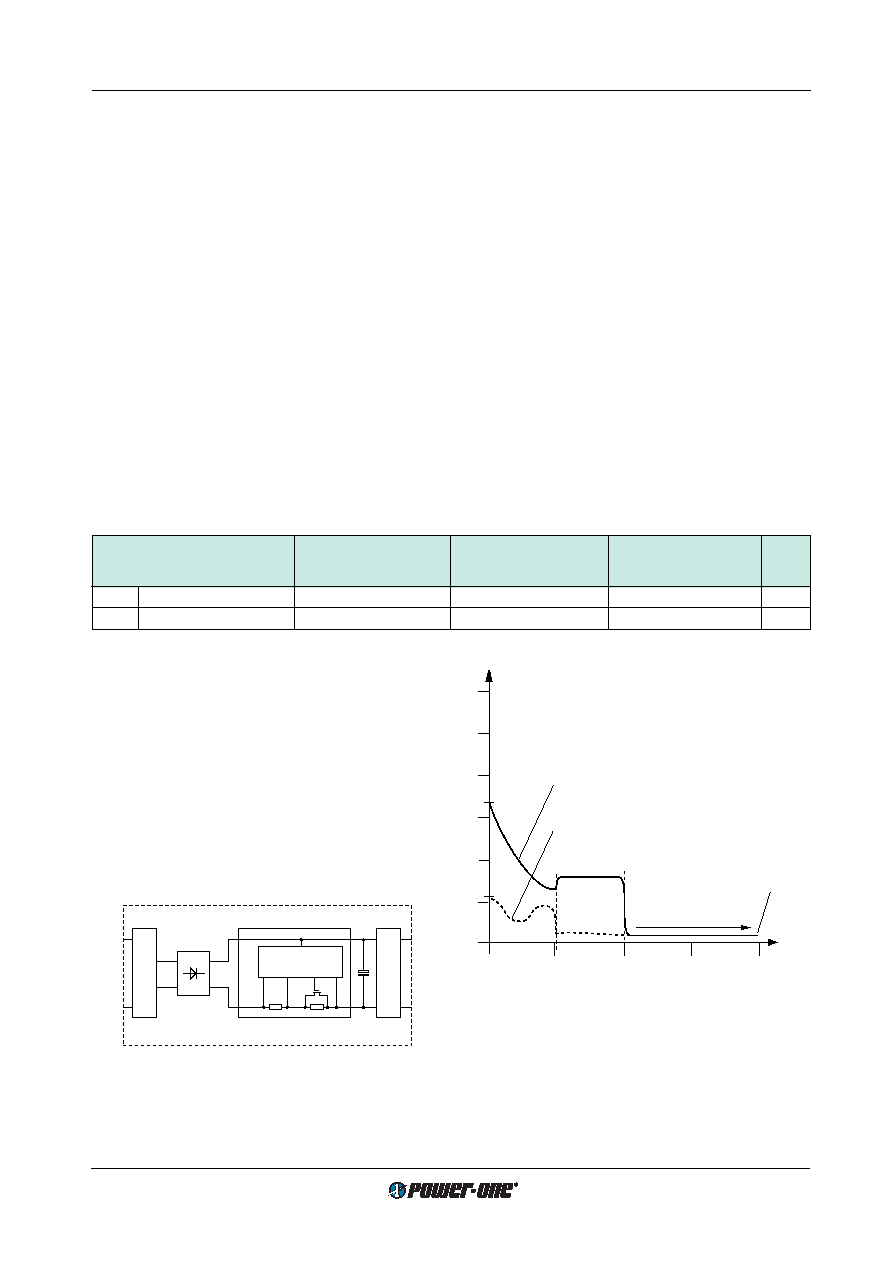
Fig. 20
Typical inrush current waveforms of CM, CMZ, EM, LM
and LMZ DC-DC converter with option E
Precautions:
In order to avoid overload of the series resistor RI the on/off
switching cycle should be limited to 12 s if switched on/off
continuously. There should not be more than 10 start-up
cycles within 20 s at a case temperature of 25
°C.
If CM and CMZ types are driven by input voltages below
35 V DC or LM and LMZ types below 100 V AC, the maxi-
mum case temperature should be derated by 10 K or the to-
tal output power should be derated by 20%. EM, LM and
LMZ units driven by DC input voltages do not need to be
derated within the full specified input voltage range.
Availability:
Option E is available for CM, EM, LM and CMZ, LMZ mod-
ules with a nominal output power of 51 W maximum.
Input
Filter
Control
Converter
FET
Ci
RI
RS
Rectifier
(LM/LMZ types)
11018
Fig. 19
Option E block diagram
Table 19: Inrush current characteristics with option E
Characteristic
CM, CMZ
EM, LM, LMZ
Unit
at
Ui = 110 V DC
at
Ui = 110 V DC
at
Ui = 372 V DC
typ
max
typ
max
typ
max
Iinr p
Peak inrush current
6.5
8
2.2
4
7.3
10
A
tinr
Inrush current duration
22
30
10
20
40
ms
E Electronic Inrush Current Limitation
Available for CM, EM, LM and CMZ, LMZ types.
The standard version of the modules CM, DM, EM, LM as
well as CMZ, DMZ, LMZ include a passive inrush current
limitation in the form of a NTC resistor.
For applications which require an improved inrush current
limitation, an active electronic circuit as shown in fig.
Option
E block diagram has been developed. Typical inrush cur-
rent waveforms of units equipped with this option are
shown below.
CM and CMZ units meet the CEPT/ETSI standards for 48 V
DC supply voltage according to ETS 300132-2 if fitted with
option E combined with option D6 (input voltage monitor-
ing). Option D6, externally adjustable via potentiometer, is
necessary to disable the converter at input voltages below
the actual service ranges, avoiding an excessive input cur-
rent when the input voltage is raised slowly according to
ETS 300132-2. Option D6 threshold level
Uti + Uhi (refer to
description of option D) should be adjusted to 36.0...40.5 V
for 48 V DC nominal supply voltage (for 60 V DC systems,
threshold should be set to 44.0...50.0 V DC). The D output
(pin 5) should be connected to the inhibit (pin 2). For appli-
cations where potentiometers are not allowed refer to op-
tion D9.
12
10
8
6
4
2
0
10
20
30
40
t [ms]
Ii [A]
tinr
Normal operation
(FET fully conducting)
Ii = Po/(Ui η)
11019
tinr
CM, CMZ at 110 V DC
EM, LM, LMZ at 372 V DC
EM, LM, LMZ at 110 V DC
F Fuse Not Accessible
The standard M units have a fuseholder containing a 5
× 20
mm fuse which is externally accessible and to be found in
the back plate near the connector. Some applications re-
quire an inaccessible fuse. Option F provides a fuse moun-
ted directly onto the main PCB inside the case.
The full self-protecting functions of the module do normally
not lead to broken fuses, except as a result of inverse polar-
ity at the input of an AM, BM, CM, FM or CMZ type or if a
power component inside fails (switching transistor, free-
wheeling diode, etc). In such cases the defective unit has to
be returned to Power-One for repair.
H Enhanced Electric Strenght Test
Electric strength test voltage output to case 2800 V DC
(2000 V AC) instead of 1400 V DC (1000 V AC).
相關(guān)PDF資料 |
PDF描述 |
|---|---|
| LMZ1301-7ERD4AH | 1-OUTPUT 50 W AC-DC REG PWR SUPPLY MODULE |
| LMZ1301-7ER | 1-OUTPUT 50 W AC-DC REG PWR SUPPLY MODULE |
| LMZ1301-7PD4F | 1-OUTPUT 50 W AC-DC REG PWR SUPPLY MODULE |
| LMZ1301-7PD9AF | 1-OUTPUT 50 W AC-DC REG PWR SUPPLY MODULE |
| LMZ1301-7PD9AH | 1-OUTPUT 50 W AC-DC REG PWR SUPPLY MODULE |
相關(guān)代理商/技術(shù)參數(shù) |
參數(shù)描述 |
|---|---|
| LMZ1301-7R | 制造商:POWER-ONE 制造商全稱(chēng):Power-One 功能描述:50 Watt AC-DC Converters |
| LMZ13608 | 制造商:TI 制造商全稱(chēng):Texas Instruments 功能描述:SIMPLE SWITCHER?? Power Module with 36V Maximum Input Voltage |
| LMZ13608EVAL/NOPB | 功能描述:電源管理IC開(kāi)發(fā)工具 LMZ13608 EVAL BOARD RoHS:否 制造商:Maxim Integrated 產(chǎn)品:Evaluation Kits 類(lèi)型:Battery Management 工具用于評(píng)估:MAX17710GB 輸入電壓: 輸出電壓:1.8 V |
| LMZ13608TZ | 制造商:TI 制造商全稱(chēng):Texas Instruments 功能描述:SIMPLE SWITCHER?? Power Module with 36V Maximum Input Voltage |
| LMZ13608TZ/NOPB | 功能描述:直流/直流開(kāi)關(guān)調(diào)節(jié)器 RoHS:否 制造商:International Rectifier 最大輸入電壓:21 V 開(kāi)關(guān)頻率:1.5 MHz 輸出電壓:0.5 V to 0.86 V 輸出電流:4 A 輸出端數(shù)量: 最大工作溫度: 安裝風(fēng)格:SMD/SMT 封裝 / 箱體:PQFN 4 x 5 |
發(fā)布緊急采購(gòu),3分鐘左右您將得到回復(fù)。