- 您現(xiàn)在的位置:買賣IC網(wǎng) > PDF目錄361043 > LMV931MFX (NATIONAL SEMICONDUCTOR CORP) 1.8V, RRIO Operational Amplifiers PDF資料下載
參數(shù)資料
| 型號: | LMV931MFX |
| 廠商: | NATIONAL SEMICONDUCTOR CORP |
| 元件分類: | 運動控制電子 |
| 英文描述: | 1.8V, RRIO Operational Amplifiers |
| 中文描述: | OP-AMP, 6000 uV OFFSET-MAX, 1.4 MHz BAND WIDTH, PDSO5 |
| 封裝: | SOT-23, 5 PIN |
| 文件頁數(shù): | 6/19頁 |
| 文件大?。?/td> | 625K |
| 代理商: | LMV931MFX |
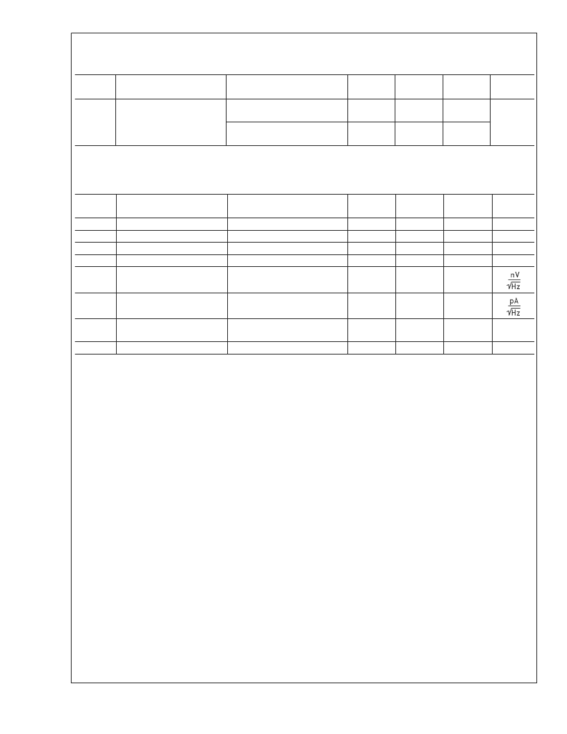
5V DC Electrical Characteristics
(Continued)
Unless otherwise specified, all limits guaranteed for T
= 25C. V
+
= 5V, V
= 0V, V
CM
= V
+
/2, V
O
= V
+
/2 and
R
L
>
1 M
.
Boldface
limits apply at the temperature extremes. See (Note 10)
Symbol
Parameter
Condition
Min
(Note 6)
80
68
58
45
Typ
(Note 5)
100
Max
(Note 6)
Units
I
O
Output Short Circuit Current
LMV931, Sourcing, V
O
= 0V
V
IN
= 100mV
Sinking, V
O
= 5V
V
IN
= 100mV
mA
65
5V AC Electrical Characteristics
Unless otherwise specified, all limits guaranteed for T
= 25C. V
+
= 5V, V
= 0V, V
CM
= V
+
/2, V
O
= 2.5V and
R
L
>
1 M
.
Boldface
limits apply at the temperature extremes. See (Note 10)
Symbol
Parameter
Conditions
Min
(Note 6)
Typ
(Note 5)
0.42
1.5
71
8
50
Max
(Note 6)
Units
SR
GBW
Φ
m
G
m
e
n
Slew Rate
Gain-Bandwidth Product
Phase Margin
Gain Margin
Input-Referred Voltage Noise
(Note 7)
V/μs
MHz
deg
dB
f = 1kHz, V
CM
= 1V
i
n
Input-Referred Current Noise
f = 1kHz
0.07
THD
Total Harmonic Distortion
f = 1kHz, A
V
= +1
R
L
= 600
, V
O
= 1 V
PP
(Note 9)
0.022
%
Amp-to-Amp Isolation
123
dB
Note 1:
Absolute Maximum Ratings indicate limits beyond which damage to the device may occur. Operating Ratings indicate conditions for which the device is
intended to be functional, but specific performance is not guaranteed. For guaranteed specifications and the test conditions, see the Electrical Characteristics.
Note 2:
Human body model, 1.5k
in series with 100pF. Machine model, 200
in series with 100pF.
Note 3:
Applies to both single-supply and split-supply operation. Continuous short circuit operation at elevated ambient temperature can result in exceeding the
maximum allowed junction temperature of 150C. Output currents in excess of 45mA over long term may adversely affect reliability.
Note 4:
The maximum power dissipation is a function of T
,
θ
, and T
. The maximum allowable power dissipation at any ambient temperature is
P
D
= (T
J(MAX)
–T
A
)/
θ
JA
. All numbers apply for packages soldered directly into a PC board.
Note 5:
Typical Values represent the most likely parametric norm.
Note 6:
All limits are guaranteed by testing or statistical analysis.
Note 7:
V
+
= 5V. Connected as voltage follower with 5V step input. Number specified is the slower of the positive and negative slew rates.
Note 8:
For guaranteed temperature ranges, see Input Common-Mode Voltage Range specifications.
Note 9:
Input referred, V
+
= 5V and R
L
= 100k
connected to 2.5V. Each amp excited in turn with 1kHz to produce V
O
= 3V
PP
.
Note 10:
Electrical Table values apply only for factory testing conditions at the temperature indicated. Factory testing conditions result in very limited self-heating
of the device such that T
J
= T
A
. No guarantee of parametric performance is indicated in the electrical tables under conditions of internal self-heating where T
J
>
T
A
.
See Applications section for information of temperature derating of the device. Absolute Maximum Ratings indicated junction temperature limits beyond which the
device may be permanently degraded, either mechanically or electrically.
L
www.national.com
6
相關PDF資料 |
PDF描述 |
|---|---|
| LMV931MG | 1.8V, RRIO Operational Amplifiers |
| LMV931MGX | 1.8V, RRIO Operational Amplifiers |
| LMV932 | 1.8V, RRIO Operational Amplifiers |
| LMX2240M | Intermediate Frequency Receiver |
| LMX2240 | Crimp Tool for Power Connectors, Male; For Use With:Molex Pitch Sabre Terminals; Wire Size (AWG):18-14 |
相關代理商/技術參數(shù) |
參數(shù)描述 |
|---|---|
| LMV931MFX/E7002670 | 制造商:Texas Instruments 功能描述: |
| LMV931MFX/NOPB | 功能描述:運算放大器 - 運放 RoHS:否 制造商:STMicroelectronics 通道數(shù)量:4 共模抑制比(最小值):63 dB 輸入補償電壓:1 mV 輸入偏流(最大值):10 pA 工作電源電壓:2.7 V to 5.5 V 安裝風格:SMD/SMT 封裝 / 箱體:QFN-16 轉換速度:0.89 V/us 關閉:No 輸出電流:55 mA 最大工作溫度:+ 125 C 封裝:Reel |
| LMV931MG | 功能描述:運算放大器 - 運放 RoHS:否 制造商:STMicroelectronics 通道數(shù)量:4 共模抑制比(最小值):63 dB 輸入補償電壓:1 mV 輸入偏流(最大值):10 pA 工作電源電壓:2.7 V to 5.5 V 安裝風格:SMD/SMT 封裝 / 箱體:QFN-16 轉換速度:0.89 V/us 關閉:No 輸出電流:55 mA 最大工作溫度:+ 125 C 封裝:Reel |
| LMV931MG/NOPB | 功能描述:運算放大器 - 運放 RRIO 1.8V SGL OPAMP RoHS:否 制造商:STMicroelectronics 通道數(shù)量:4 共模抑制比(最小值):63 dB 輸入補償電壓:1 mV 輸入偏流(最大值):10 pA 工作電源電壓:2.7 V to 5.5 V 安裝風格:SMD/SMT 封裝 / 箱體:QFN-16 轉換速度:0.89 V/us 關閉:No 輸出電流:55 mA 最大工作溫度:+ 125 C 封裝:Reel |
| LMV931MG/NOPB | 制造商:Texas Instruments 功能描述:Operational Amplifier (Op-Amp) IC |
發(fā)布緊急采購,3分鐘左右您將得到回復。