- 您現(xiàn)在的位置:買賣IC網(wǎng) > PDF目錄361035 > LM9831 (National Semiconductor Corporation) LM9831 42-Bit Color, 1200dpi USB Image Scanner PDF資料下載
參數(shù)資料
| 型號: | LM9831 |
| 廠商: | National Semiconductor Corporation |
| 英文描述: | LM9831 42-Bit Color, 1200dpi USB Image Scanner |
| 中文描述: | LM9831 42位彩色,1200dpi的USB圖像掃描儀 |
| 文件頁數(shù): | 14/41頁 |
| 文件大?。?/td> | 320K |
| 代理商: | LM9831 |
第1頁第2頁第3頁第4頁第5頁第6頁第7頁第8頁第9頁第10頁第11頁第12頁第13頁當(dāng)前第14頁第15頁第16頁第17頁第18頁第19頁第20頁第21頁第22頁第23頁第24頁第25頁第26頁第27頁第28頁第29頁第30頁第31頁第32頁第33頁第34頁第35頁第36頁第37頁第38頁第39頁第40頁第41頁

14
www.national.com
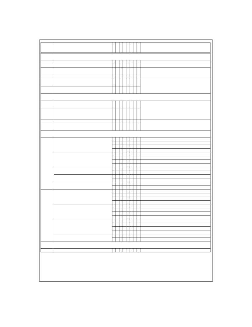
SENSOR PIXEL CONFIGURATION
1C
1D
Optical Black Pixels Start
Optical Black Pixels End
n n n n n n n n n pixels (0 - 255)
n n n n n n n n n pixels (0 - 255)
1E
Active Pixels Start - MSB
n n n n n n n pixels (0 - 16383)
Set to the same value as register
Data Pixels Start
.
n n n n n n n n
n n n n n nThis selects the pixel count at which the current line is
ended and the next line begins. This determines the
integration time of one line.
1F
Active Pixels Start - LSB
20
Line End - MSB
21
Line End - LSB
n n n n n n n n
PIXEL DATA RANGE TO PROCESS
22
Data Pixels Start - MSB
n n n n n n
n pixels (
Active Pixels Start
- 16383)
This selects the start of the range of pixels transmitted
to the PC and determines the pixel location where
offset and shading correction begins (pixel 0 in the
DataPort). This value must be >=
Active Pixels Start
n n n n n n n pixels (
Data Pixels Start
- [
Line End
- 20])
This selects the end of the range of pixels transmitted
to the PC. This value must be <= [
Line End
- 20]
23
Data Pixels Start - LSB
n n n n n n n n
24
Data Pixels End - MSB
25
Data Pixels End - LSB
n n n n n n n n
COLOR MODE SETTINGS
26
AFE Operation
3 Channel or 1 Channel
0 0 0 3 Channel Pixel Rate Color
0 0 1 3 Channel Line Rate Color
1 0 0 1 Channel Grayscale
1 0 1 1 Channel Color
Red Channel
Green Channel
Blue Channel
N/A
1st TR pulse position (inside 1 high)
2nd TR pulse position (inside 1 low)
1st TR pulse position (inside 1 high)
2nd TR pulse position (inside 1 low)
1st TR pulse position (inside 1 high)
2nd TR pulse position (inside 1 low)
0 0 Do not drop any TR
RED
pulses
0 1 Drop 1 TR
RED
pulse (double integration time)
1 0 Drop 2 TR
RED
pulses (triple integration time)
1 1 N/A
0 0
Do not drop any TR
GREEN
pulses
0 1
Drop 1 TR
GREEN
pulse (double integration time)
1 0
Drop 2 TR
GREEN
pulses (triple integration time)
1 1
N/A
Do not drop any TR
BLUE
pulses
Drop 1 TR
BLUE
pulse (double integration time)
Drop 2 TR
BLUE
pulses (triple integration time)
N/A
Normal operation
Outputs single TR pulse on TR1, TR2, and CP2 pins
1 Channel Grayscale Input Source
(1 Channel Color always uses the
Blue Channel as the input)
0 0
0 1
1 0
1 1
TR
RED
(=TR1) position
(3 Channel Line Rate Mode only)
TR
GREEN
(=TR2) position
(3 Channel Line Rate Mode only)
TR
BLUE
(=CP2) position
(3 Channel Line Rate Mode only)
0
1
0
1
0
1
27
3 Channel Line Rate TR
RED
drop
(3 Channel Line Rate Mode only)
3 Channel Line Rate TR
GREEN
drop
(3 Channel Line Rate Mode only)
3 Channel Line Rate TR
BLUE
drop
(3 Channel Line Rate Mode only)
0 0
0 1
1 0
1 1
Triple TR output
0
1
RESERVED
28
Reserved
0 0 0 0 0 0 0 0 Write 00 to this register
Address
Function
D
7
D
6
D
5
D
4
D
3
D
2
D
1
D
0
Value
相關(guān)PDF資料 |
PDF描述 |
|---|---|
| LM9831CCVJDX | LM9831 42-Bit Color, 1200dpi USB Image Scanner |
| LM9832CCVJD | LM9832 42-Bit Color, 1200dpi USB Image Scanner |
| LM9832 | LM9832 42-Bit Color, 1200dpi USB Image Scanner |
| LM9833CCVJD | LM9833 48-Bit Color, 1200dpi USB Image Scanner |
| LM9833 | LM9833 48-Bit Color, 1200dpi USB Image Scanner |
相關(guān)代理商/技術(shù)參數(shù) |
參數(shù)描述 |
|---|---|
| LM9831CCVJD | 制造商:NSC 制造商全稱:National Semiconductor 功能描述:LM9831 42-Bit Color, 1200dpi USB Image Scanner |
| LM9831CCVJDX | 制造商:NSC 制造商全稱:National Semiconductor 功能描述:LM9831 42-Bit Color, 1200dpi USB Image Scanner |
| LM9832 | 制造商:NSC 制造商全稱:National Semiconductor 功能描述:LM9832 42-Bit Color, 1200dpi USB Image Scanner |
| LM9832B-B WAF | 制造商:Texas Instruments 功能描述: |
| LM9832B-E WAF | 制造商:Texas Instruments 功能描述: |
發(fā)布緊急采購,3分鐘左右您將得到回復(fù)。