- 您現(xiàn)在的位置:買賣IC網(wǎng) > PDF目錄385489 > LM8333 (NATIONAL SEMICONDUCTOR CORP) Keypad Controller with I/O Expansion and ACCESS.bus Host Interface PDF資料下載
參數(shù)資料
| 型號: | LM8333 |
| 廠商: | NATIONAL SEMICONDUCTOR CORP |
| 元件分類: | 微控制器/微處理器 |
| 英文描述: | Keypad Controller with I/O Expansion and ACCESS.bus Host Interface |
| 中文描述: | SPECIALTY MICROPROCESSOR CIRCUIT, BGA49 |
| 封裝: | MICRO, BGA-49 |
| 文件頁數(shù): | 10/17頁 |
| 文件大小: | 768K |
| 代理商: | LM8333 |
7.0 Device Operation
(Continued)
7.3 HOST COMMAND EXECUTION
7.3.1 Command Structure
All communication with the LM8333 over the ACCESS.bus
interface is initiated by the host, usually in response to an
interrupt request (IRQ low) asserted by the LM8333.
Figure
7
shows a sequence of Start conditions, slave addresses,
READ_INT command (0xD0), acknowledge cycles, data
bytes, and Stop condition for reading the interrupt code.
Every transfer is preceded by a Start condition (S) or a
Repeated Start condition (RS). The latter occurs when a
command follows immediately upon another command with-
out an intervening Stop condition (P). A Stop condition indi-
cates the end of transmission. Every byte is acknowledged
(A) by the receiver.
The first byte in a write from the host to the LM8333 is 0xA2,
and the first byte in a read is 0xA3. This byte is composed of
a 7-bit slave address in bits 7:1 and a direction bit in bit 0.
The direction bit is 0 on writes from the host to the slave and
1 on reads from the slave to the host.
The second byte sends the command. The commands are
listed in
Table 5
. In the example, the READ_INT command
(0xD0) reads the interrupt code.
The slave address is repeated in the third byte, with the
direction bit set to 1. The Start (or Repeated Start) condition
must be repeated whenever the slave address or the direc-
tion bit is changed. In this case, the direction bit is changed.
The data is sent from the slave to the host in the fourth byte.
When the master is the receiver, it sends a negative ac-
knowledgement (NA) to indicate the end of the data.
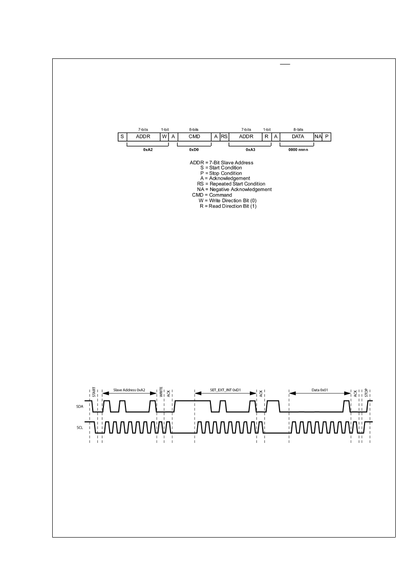
7.4 HOST WRITE COMMANDS
Some host commands include one or more data bytes writ-
ten to the LM8333.
Figure 8
shows a SET_EXT_INT com-
mand, which consists of an address byte, a command byte,
and one data byte.
The first byte is composed of a 7-bit slave address in bits 7:1
and a direction bit in bit 0. The state of the direction bit is 0
on writes from the host to the slave and 1 on reads from the
slave to the host.
The second byte sends the command. The commands are
listed in
Figure 9
. The SET_EXT_INT command is 0xD1.
The third byte send the data, in this case configuring GE-
N_IO_0 as an external interrupt input.
7.5 HOST READ COMMANDS
Some host commands include one or more data bytes read
from the LM8333.
Figure 9
shows a READ_INT command
which consists of an address byte, a command byte, a
second address byte, and a data byte.
The first address byte is sent with the direction bit driven low
to indicate a write transaction of the command to the
LM8333. The second address byte is sent with the direction
bit undriven (pulled high) to indicate a read transaction of the
data from the LM8333.
The Start (or Repeated Start) condition must be repeated
whenever the slave address or the direction bit is changed.
In this case, the direction bit is changed.
20210609
FIGURE 7. Typical Command Sequence from Host
20210610
FIGURE 8. Host Write Command
L
www.national.com
10
相關PDF資料 |
PDF描述 |
|---|---|
| LM8400 | Four Wire Resistive Touchscreen Controller with Brownout |
| LM8500 | Four Wire Resistive Touchscreen Controller with Brownout |
| LM8500HLQ9 | Four Wire Resistive Touchscreen Controller with Brownout |
| LM8500HMT9 | Four Wire Resistive Touchscreen Controller with Brownout |
| LM8500HVA9 | Four Wire Resistive Touchscreen Controller with Brownout |
相關代理商/技術參數(shù) |
參數(shù)描述 |
|---|---|
| LM8333_07 | 制造商:NSC 制造商全稱:National Semiconductor 功能描述:Mobile I/O Companion Supporting Key-Scan, I/O Expansion, PWM, and ACCESS.bus Host Interface |
| LM8333EVALKIT | 功能描述:其他開發(fā)工具 LM8333 AND SOFTWARE EVAL KIT RoHS:否 制造商:Parallax 產(chǎn)品:ELEV-8 Hex Upgrade Kits 類型:Robotics 工具用于評估:ELEV-8 Quadcopter 工作電源電壓: |
| LM8333FLQ8X | 制造商:NSC 制造商全稱:National Semiconductor 功能描述:Mobile I/O Companion Supporting Key-Scan, I/O Expansion, PWM, and ACCESS.bus Host Interface |
| LM8333FLQ8X/NOPB | 功能描述:接口 - 專用 RoHS:否 制造商:Texas Instruments 產(chǎn)品類型:1080p60 Image Sensor Receiver 工作電源電壓:1.8 V 電源電流:89 mA 最大功率耗散: 最大工作溫度:+ 85 C 安裝風格:SMD/SMT 封裝 / 箱體:BGA-59 |
| LM8333FLQ8Y | 制造商:Texas Instruments 功能描述:Mobile I/O Companion Supporting Key Scan 32-Pin LLP EP |
發(fā)布緊急采購,3分鐘左右您將得到回復。