- 您現(xiàn)在的位置:買賣IC網(wǎng) > PDF目錄361034 > LM78 (National Semiconductor Corporation) Microprocessor System Hardware Monitor PDF資料下載
參數(shù)資料
| 型號: | LM78 |
| 廠商: | National Semiconductor Corporation |
| 英文描述: | Microprocessor System Hardware Monitor |
| 中文描述: | 微處理器系統(tǒng)硬件監(jiān)視器 |
| 文件頁數(shù): | 24/31頁 |
| 文件大小: | 424K |
| 代理商: | LM78 |
第1頁第2頁第3頁第4頁第5頁第6頁第7頁第8頁第9頁第10頁第11頁第12頁第13頁第14頁第15頁第16頁第17頁第18頁第19頁第20頁第21頁第22頁第23頁當前第24頁第25頁第26頁第27頁第28頁第29頁第30頁第31頁
Functional Description
(Continued)
REGISTERS AND RAM
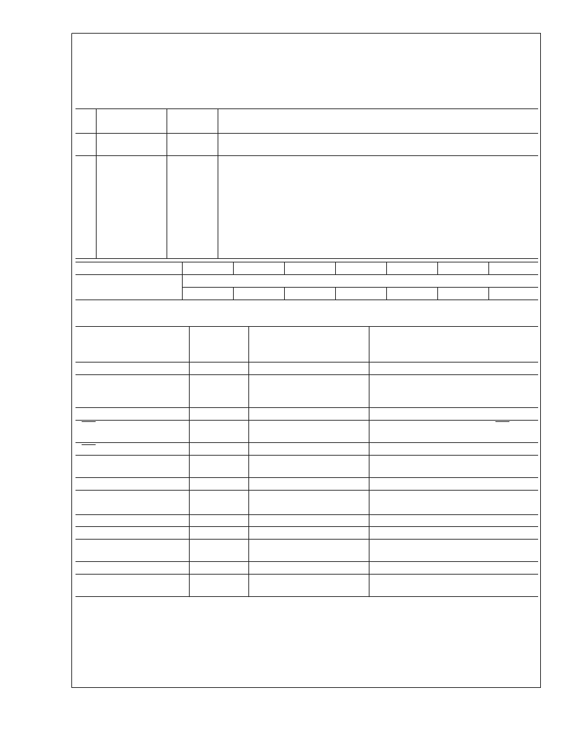
13.1 Address Register (Port x5h)
The main register is the ADDRESS Register located at Port x5h. The bit designations are as follows:
Bit
Name
Read/
Write
Read/Write
Description
6-0
Address
Pointer
Busy
Address of RAM and Registers. See the tables below for detail.
7
Read
Only
A one indicates the device is busy because of a Serial Bus transaction or another ISA
bus transaction. With checking this bit, multiple ISA drivers can use LM78 without
interfering with each other or a Serial Bus driver.
It is the user’s responsibility not to have a Serial Bus and ISA bus operations at the
same time.
This bit is:
Set:
with a write to Port x5h or when a Serial Bus transaction is in progress.
Reset:
with a write or read from Port x6h if it is set by a write to Port x5h, or when the
Serial Bus transaction is finished.
Bit 7
Busy
Bit 6
Bit 5
Bit 4
Bit 3
Bit 2
Bit 1
Bit 0
Address Pointer (Power On default 00h)
A4
A3
(Power On default 0)
A6
A5
A2
A1
A0
Address Pointer Index (A6–A0)
Registers and RAM
A6–A0 in
Hex
Power On Value of
Registers:
<
7:0
>
in Binary
0000 1000
0000 0000
Notes
Configuration Register
Interrupt Status Register 1
40h
41h
Auto-increment to the address of Interrupt
Status Register 2 after a read or write to
Port x6h.
Interrupt Status Register 2
SMI Mask Register 1
42h
43h
0000 0000
0000 0000
Auto-increment to the address of SMI Mask
Register 2 after a read or write to Port x6h.
SMI Mask Register 2
NMI Mask Register 1
44h
45h
0000 0000
0000 0000
Auto-increment to the address of NMI Mask
Register 2 after a read or write to Port x6h.
NMI Mask Register 2
VID/Fan Divisor Register
46h
47h
0100 0000
<
7:4
>
= 0101;
<
3:0
>
= VID3–VID0
0010 1101
0100 0000
Serial Bus Address Register
Chip Reset/ID Register
POST RAM
48h
49h
00–1Fh
Auto-increment to the next location after a
read or write to Port x6h and stop at 1Fh.
Value RAM
Value RAM
20–3Fh
60–7Fh
Auto-increment to the next location after a
read or write to Port x6h and stop at 7Fh.
L
www.national.com
24
相關(guān)PDF資料 |
PDF描述 |
|---|---|
| LM78CCVF | Microprocessor System Hardware Monitor |
| LM78CCVF-J | Microprocessor System Hardware Monitor |
| LM79CCVF | Microprocessor System Hardware Monitor |
| LM79 | |
| LM81CIMTX-32 | Serial Interface ACPI-Compatible Microprocessor System |
相關(guān)代理商/技術(shù)參數(shù) |
參數(shù)描述 |
|---|---|
| LM780 | 制造商:LM TECHNOLOGIES 功能描述:MODULE BT2.1 CLASS1 CSR BC04 W/ANT 制造商:LM TECHNOLOGIES 功能描述:MODULE, BT2.1 CLASS1, CSR BC04 W/ANT |
| LM7800 | 制造商:未知廠家 制造商全稱:未知廠家 功能描述:3-Terminal Positive Regulators(324.81 k) |
| LM7800-220M | 制造商:SEME-LAB 制造商全稱:Seme LAB 功能描述:POSITIVE VOLTAGE REGULATOR TO 220 M |
| LM7800C | 制造商:NSC 制造商全稱:National Semiconductor 功能描述:Series 3-Terminal Positive Regulators |
| LM7800-SMD | 制造商:SEME-LAB 制造商全稱:Seme LAB 功能描述:POSITIVE VOLTAGE REGULATOR TO 220 M |
發(fā)布緊急采購,3分鐘左右您將得到回復(fù)。