- 您現(xiàn)在的位置:買(mǎi)賣(mài)IC網(wǎng) > PDF目錄369795 > LM6321MX Analog Buffer/Voltage Follower PDF資料下載
參數(shù)資料
| 型號(hào): | LM6321MX |
| 英文描述: | Analog Buffer/Voltage Follower |
| 中文描述: | 模擬緩沖器/電壓跟隨 |
| 文件頁(yè)數(shù): | 6/10頁(yè) |
| 文件大小: | 208K |
| 代理商: | LM6321MX |

Application Hints
HEATSINK REQUIREMENTS
A heatsink may be required with the LM6321 depending on
the maximum power dissipation and maximum ambient tem-
perature of the application. Under all possible operating
conditions, the junction temperature must be within the
range specified under Absolute Maximum Ratings.
To determine if a heatsink is required, the maximum power
dissipated by the buffer, P(max), must be calculated. The
formula for calculating the maximum allowable power dissi-
pation in any application is P
D
e
(T
J
(max)
b
T
A
)/
i
JA
. For
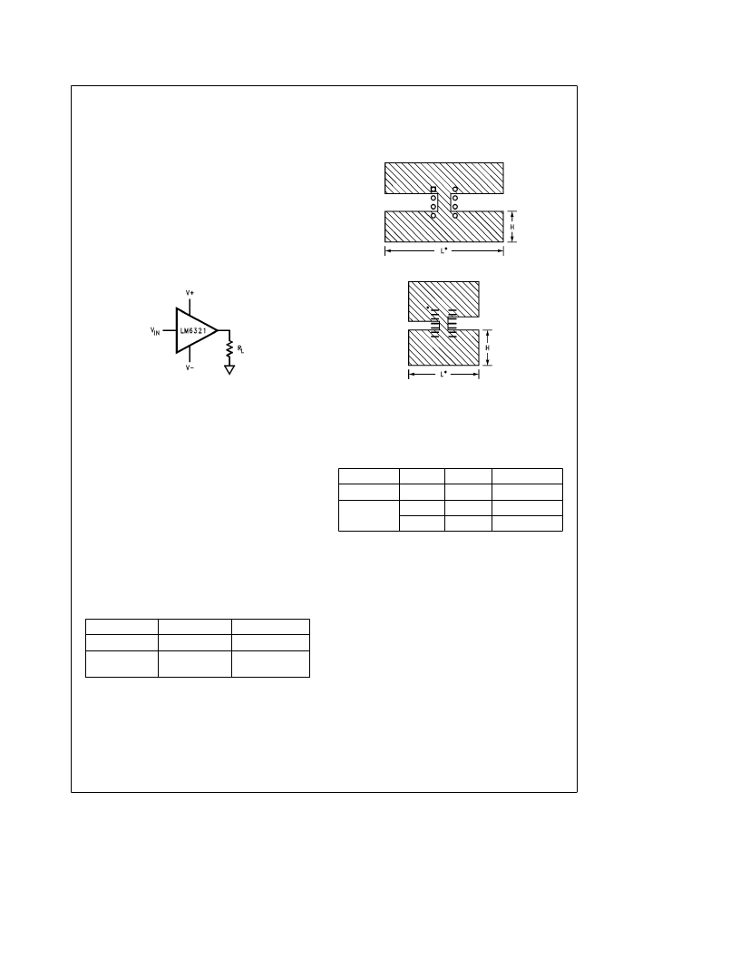
the simple case of a buffer driving a resistive load as in
Figure 2, the maximum DC power dissipation occurs when
the output is at half the supply. Assuming equal supplies,
the formula is P
D
e
I
S
(2V
a
)
a
V
a
2
/2 R
L
.
TL/H/9223–8
FIGURE 2
Figure 3 shows copper patterns which may be used to dissi-
pate heat from the LM6321.
8-Pin DIP
TL/H/9223–9
14-Pin SO
TL/H/9223–10
*
For best results, use L
e
2H
FIGURE 3. Copper Heatsink Patterns
The next parameter which must be calculated is the maxi-
mum allowable temperature rise, T
R
(max). This is calculat-
ed by using the formula:
T
R
(max)
e
T
J
(max)
b
T
A
(max)
where: T
J
(max) is the maximum allowable junction tempera-
ture
T
A
(max) is the maximum ambient temperature
Using the calculated values for T
R
(max) and P(max), the
required value for junction-to-ambient thermal resistance,
i
(J–A)
, can now be found:
i
(J–A)
e
T
R
(max)/P(max)
The heatsink for the LM6321 is made using the PC board
copper. The heat is conducted from the die, through the
lead frame (inside the part), and out the pins which are sol-
dered to the PC board. The pins used for heat conduction
are:
TABLE I
Part
Package
Pins
LM6321N
8-Pin DIP
1, 4, 5, 8
LM6321M
14-Pin SO
1, 2, 3, 6, 7,
8, 9, 13, 14
Table II shows some values of junction-to-ambient thermal
resistance (
i
J–A
) for values of L and W for 2 oz. copper:
TABLE II
Package
L (in.)
H (in.)
i
J–A
(
§
C/W)
8-Pin DIP
2
0.5
47
14-Pin SO
1
0.5
69
2
1
57
6
相關(guān)PDF資料 |
PDF描述 |
|---|---|
| LM6325 | |
| LM6402H | |
| LM6402L | |
| LM6405A | |
| LM6405H | |
相關(guān)代理商/技術(shù)參數(shù) |
參數(shù)描述 |
|---|---|
| LM6321N | 制造商:National Semiconductor Corporation 功能描述:Voltage Follower, Single, 8 Pin, Plastic, DIP |
| LM6325 | 制造商:未知廠(chǎng)家 制造商全稱(chēng):未知廠(chǎng)家 功能描述: |
| LM6325N | 制造商:NSC 制造商全稱(chēng):National Semiconductor 功能描述:High Speed Buffer |
| LM632-DA | 功能描述:基本/快動(dòng)開(kāi)關(guān) Foot Switch RoHS:否 制造商:Omron Electronics 觸點(diǎn)形式:SPDT 執(zhí)行器:Lever 電流額定值:5 A 電壓額定值 AC:250 V 電壓額定值 DC:30 V 功率額定值: 工作力:120 g IP 等級(jí):IP 67 NEMA 額定值: 端接類(lèi)型:Wire 安裝:Panel |
| LM632-DC3A | 功能描述:基本/快動(dòng)開(kāi)關(guān) Foot Switch RoHS:否 制造商:Omron Electronics 觸點(diǎn)形式:SPDT 執(zhí)行器:Lever 電流額定值:5 A 電壓額定值 AC:250 V 電壓額定值 DC:30 V 功率額定值: 工作力:120 g IP 等級(jí):IP 67 NEMA 額定值: 端接類(lèi)型:Wire 安裝:Panel |
發(fā)布緊急采購(gòu),3分鐘左右您將得到回復(fù)。